CMS |
| 6. WIRING AND SETTING UP: | |||
| |||||
|
| 1 |
| Open the wiring cover at the back of the speaker can to access the Euro type connector | |
|
|
| |||
|
|
|
| ||
|
|
|
|
| plug and socket. |
|
|
|
|
|
|
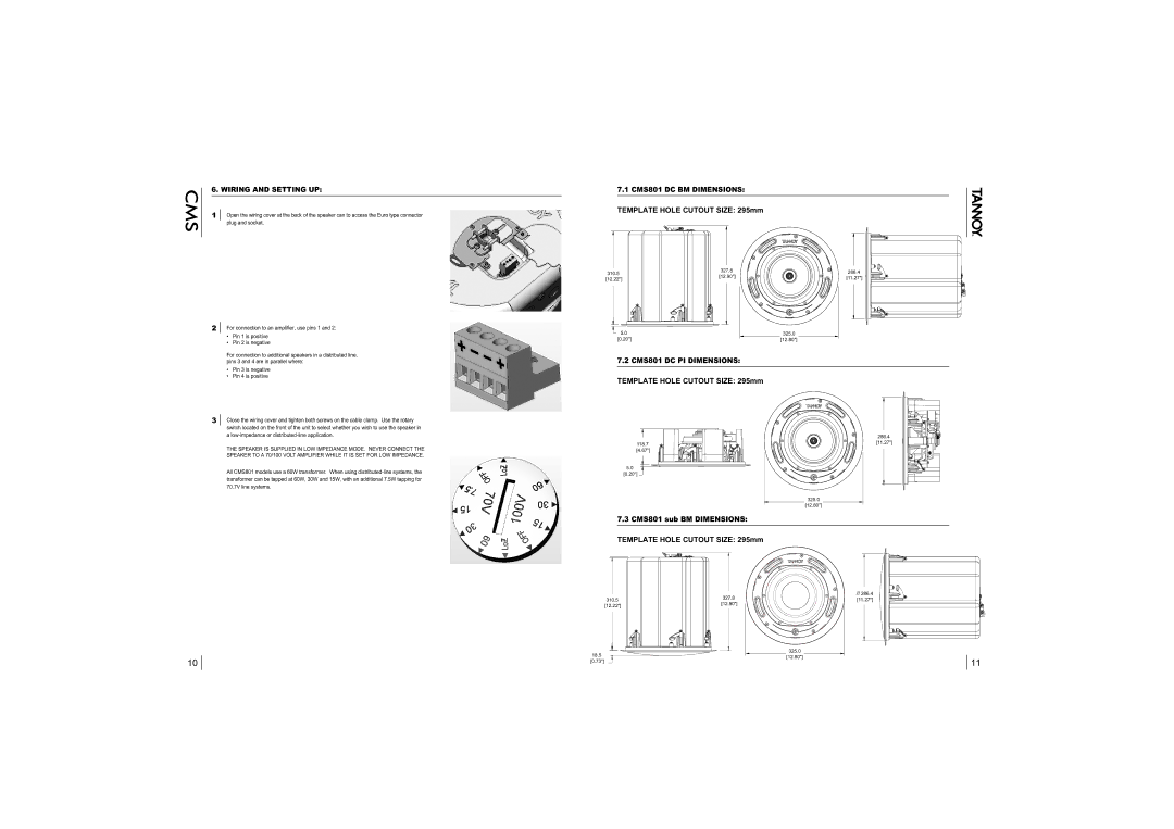
7.1 CMS801 DC BM DIMENSIONS:
TEMPLATE HOLE CUTOUT SIZE: 295mm
310.5
327.8
286.4
[12.22"]
[12.90"]
[11.27"]
2For connection to an amplifier, use pins 1 and 2:
•Pin 1 is positive
•Pin 2 is negative
5.0
[0.20"]
325.0
[12.80"]
For connection to additional speakers in a distributed line, pins 3 and 4 are in parallel where:
•Pin 3 is negative
•Pin 4 is positive
7.2 CMS801 DC PI DIMENSIONS:
TEMPLATE HOLE CUTOUT SIZE: 295mm
3Close the wiring cover and tighten both screws on the cable clamp. Use the rotary switch located on the front of the unit to select whether you wish to use the speaker in a
THE SPEAKER IS SUPPLIED IN LOW IMPEDANCE MODE. NEVER CONNECT THE SPEAKER TO A 70/100 VOLT AMPLIFIER WHILE IT IS SET FOR LOW IMPEDANCE.
All CMS801 models use a 60W transformer. When using
118.7
[4.67"]
5.0![]()
[0.20"]
7.3CMS801 sub BM DIMENSIONS:
286.4
[11.27"]
325.0
[12.80"]
10
TEMPLATE HOLE CUTOUT SIZE: 295mm
| 327.8 | 286.4 | |
310.5 | [11.27"] | ||
[12.90"] | |||
[12.22"] |
| ||
|
|
18.5 | 325.0 |
[12.80"] | |
[0.73"] | 11 |
|