4.INCORPORATION OF DGPS BEACON RECEIVER KIT (for
5.Close the cover of
6.Plug
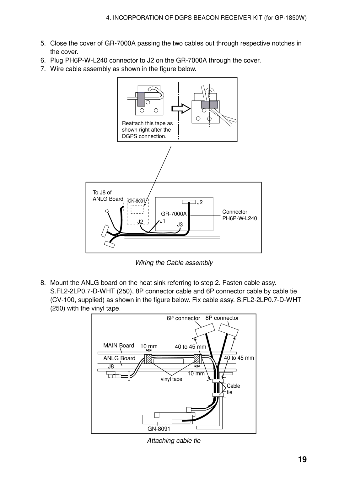
7.Wire cable assembly as shown in the figure below.
Reattach this tape as shown right after the DGPS connection.
To J8 of ANLG Board
J2
J2
J1
J3
Connector
Wiring the Cable assembly
8.Mount the ANLG board on the heat sink referring to step 2. Fasten cable assy.
|
| 6P connector | 8P connector |
MAIN Board | 10 mm | 40 to 45 mm | |
ANLG Board |
|
| 40 to 45 mm |
J8 |
|
|
|
|
| 10 mm |
|
|
| vinyl tape |
|
|
|
| Cable |
|
|
| tie |
|
| ||
Attaching cable tie
19