Manuals
/
Tappan
/
Kitchen Appliance
/
Range
Tappan
318200409 Installation Instructions, Clearances and Dimensions, Electrical Hook-Up, Front
Models:
318200409
1
6
48
48
Download
48 pages
46.19 Kb
3
4
5
6
7
8
9
10
Install
Indicator Light
Warranty
Dimension
Problem
Tableau des commandes
Setting Surface Controls
Self-Cleaning Ovens
Safety
Avoid Service Check List
Page 6
Image 6
Page 5
Page 7
Page 6
Image 6
Page 5
Page 7
Contents
OWNERS GUIDE
ELECTRIC RANGES
READ AND SAVE THESE INSTRUCTIONS
318200409 Rev A
FRIGIDAIRE PARTS AND SERVICE
WARRANTY
ELECTRIC RANGES
WARRANTY PERIOD
PLEASE DO THIS NOW
G e n e r a l I n f o r m a t i o n
SOME MODELS
The self-addressed PRODUCT
Do not use the oven for storage
IMPORTANT INSTRUCTIONS FOR USING
IMPORTANT SAFETY INSTRUCTIONS
DO NOT TOUCH SURFACE UNITS, AREAS NEAR THESE
IMPORTANT INSTRUCTIONS FOR USING YOUR OVEN
IMPORTANT SAFETY INSTRUCTIONS continued
IMPORTANT INSTRUCTIONS FOR CLEANING YOUR RANGE
SAVE THESE INSTRUCTIONS
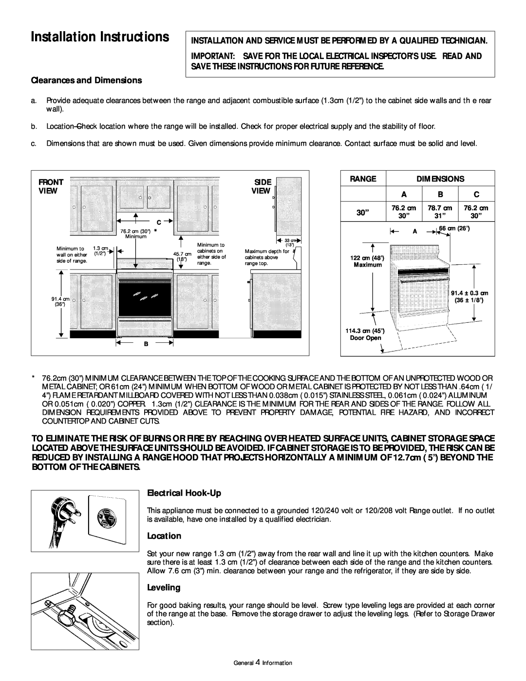
IMPORTANT SAVE FOR THE LOCAL ELECTRICAL INSPECTOR’S USE. READ AND
Installation Instructions
Clearances and Dimensions
SAVE THESE INSTRUCTIONS FOR FUTURE REFERENCE
SURFACE LIGHT REPLACEMENT some models
Installation Instructions continued
Do not turn the oven light on during the self-cleaning cycle
Oven Light
Selecting Surface Cooking Utensils
Setting Surface Controls
Circuit Protection
GOOD
Convection Cooking
Convection Roasting some models
Air Circulation in the Oven
Convection notes
Oven Baking
Indicator Light
Baking Problems and Solutions Chart
Problems
Broiling
Oven Settings
Broiler Clean-Up Tips
Preheating
REGULAR RADIANT HEATING UNITS some models
Ceramic Glass Cooktop some models
TYPES OF HEATING UNITS USED
EXPANDABLE RADIANT HEATING UNITS some models
THINGS TO REMEMBER
HOT SURFACE INDICATOR LIGHT
SPECIAL CAUTION FOR ALUMINUM FOIL AND ALUMINUM COOKING UTENSILS
USE AND CARE OF GLASS SURFACE
USE AND CARE OF GLASS SURFACE continued
CLEANING MATERIALS FOR CERAMIC GLASS COOKTOP
SPECIAL CLEANING INSTRUCTIONS FOR MINERAL DEPOSITS AND DISCOLORATIONS
DO USE ON CERAMIC GLASS COOKTOP
CLEANING AGENTS
Cleaning the Appliance
Exterior Cleaning
Control Panel
PORCELAIN ENAMEL COOKTOP CLEANING
Cleaning the Appliance continued
Porcelain enamel cooktop cleaning instructions
DAILY CLEANING For normal soil
Preparing the Oven for Self-Cleaning
Cleaning the Regular Oven Non self-clean oven
Cleaning the Self-Clean Oven some models
Adhere to the following cleaning precautions
To Remove and Replace the Oven Door
What to Expect During Cleaning
Setting the Controls for a Clean Cycle
AUTOMATIC LOCK OFF OF THE SURFACE ELEMENTS
To remove the external door glass panel
Removable Outer Door Glass Panel some models
To Remove/Replace Storage Drawer
To replace the external door panel
Staple or clip original invoice here
General 18 Information
INSTALLATION
AVOID SERVICE CHECK LIST
Before you call for service - read this
PROBLEM
RANGE DOES NOT OPERATE continued
SURFACE UNITS
CERAMIC GLASS COOKTOP some models
POOR BAKING RESULTS
SELF-CLEANING OVEN some models
BROILING
AVOID TRANSPORTATION DAMAGE TO YOUR RANGE
CUISINIÈRES ÉLECTRIQUES
LISEZ ET CONSERVEZ CES INSTRUCTIONS
GUIDE DE LUTILISATEUR
FRIGIDAIRE - PIÈCES ET SERVICE
GARANTIE
CUISINIÈRES ÉLECTRIQUES
GARANT
I n f o r m a t i o n s g é n é r a l e s
IMPORTANTES MESURES DE SÉCURITÉ
N’utilisez pas la cuisinière pour entreposer des articles
POUR L’UTILISATION DE VOTRE SURFACE DE CUISSON
IMPORTANTES MESURES DE SÉCURITÉ suite
INSTRUCTIONS DE SÉCURITÉ IMPORTANTES
POUR SURFACE DE CUISSON VITROCÉRAMIQUE SEULEMENT
Emplacement
Instructions d’installation
Espaces prévus et dimensions
Branchement
Lampe de surface
Instructions d’installation suite
Lampe du four
certain modèles
Choix des ustensiles de cuisine pour la cuisson sur les foyers
Réglage des commandes des foyers de surface
Coupe-circuit de protection
MAUVAIS
Cuisson par convection
Rôtissage par convection certains modèles
Circulation d’air dans le four
option disponible avec certains modèles
Cuisson au four
Tableau des Problèmes de cuisson au four et de leurs Solutions
Voyants lumineux
Solutions
Préchauffage
Cuisson au gril
Réglage du four
Pour la cuisson au gril
TYPES DE FOYERS UTILISÉS
FOYERS À ÉLÉMENT RADIANT DE DIMENSIONS VARIABLES certains modèles
Surface de cuisson vitrocéramique certains modèles
FOYERS À ÉLÉMENT RADIANT RÉGULIER certains modèles
PRÉCAUTIONS À PRENDRE AVEC L’EMPLOI DE PAPIER
Surface de cuisson vitrocéramique certains modèles suite
VOYANT AVERTISSEUR DE SURFACE CHAUDE
D’ALUMINIUM ET DE RÉCIPIENTS EN ALUMINIUM
NETTOYEURS APPROUVÉS POUR LA SURFACE DE CUISSON VITROCÉRAMIQUE
certains modèles suite
COMMENT NETTOYER LA SURFACE DE CUISSON VITROCÉRAMIQUE
À NE PAS UTILISER SUR LA SURFACE DE CUISSON VITROCÉRAMIQUE
Nettoyage extérieur
Tableau des commandes
Nettoyage de l’appareil
Surface de cuisson à foyers spiralés certains modèles
NETTOYAGE QUOTIDIEN Pour la saleté normale
Nettoyage de l’appareil suite
NETTOYAGE DE LA SURFACE DE CUISSON EN ÉMAIL VITRIFIÉ
Pour la saleté tenace et les taches calcinées
Préparation du four avant l’autonettoyage
Nettoyage du four régulier four non autonettoyant
Nettoyage du four autonettoyant certains modèles
Prenez les précautions de nettoyage qui suivent
Ce qui peut survenir durant l’autonettoyage
Enlever et réinstaller la porte
Réglage des commandes du four
Table de cuisson levable certains modèles
Retirer/replacer le tiroir de rangement
Pour réinstaller la vitre extérieure de la porte
Porte avec vitre extérieure démontable certains modèles
Pour retirer la vitre extérieure de la porte
Brocher ici votre facture
Informations 18 générales
LISTE DES VÉRIFICATIONS PRÉVENTIVES
Avant d’appeler un technicien de service lisez ce qui suit
PROBLÈMECAUSE POSSIBLE / SOLUTION
LA CUISINIÈRE NE FONCTIONNE PAS
LA CUISINIÈRE NE FONCTIONNE PAS suite
SURFACE DE CUISSON
SURFACE DE CUISSON VITROCÉRAMIQUE certains modèles
MAUVAIS RÉSULTATS DE CUISSON AU FOUR
AUTONETTOYAGE DU FOUR certains modèles
CAUSE POSSIBLE / SOLUTION
CUISSON AU GRIL
ÉVITEZ D’ENDOMMAGER L’APPAREIL DURANT SON TRANSPORT
Top
Page
Image
Contents