Data Sheet: Xeta iHG48070A033V, 3.3V/70A Output Half Brick Series
Thermal Management:
An important part of the overall system design process is thermal management; thermal design must be considered at all levelstoensuregoodreliabilityandlifetime ofthefinalsystem.Superiorthermaldesign and the ability to operate in severe application environments are key elements ofarobust,reliablepowermodule.
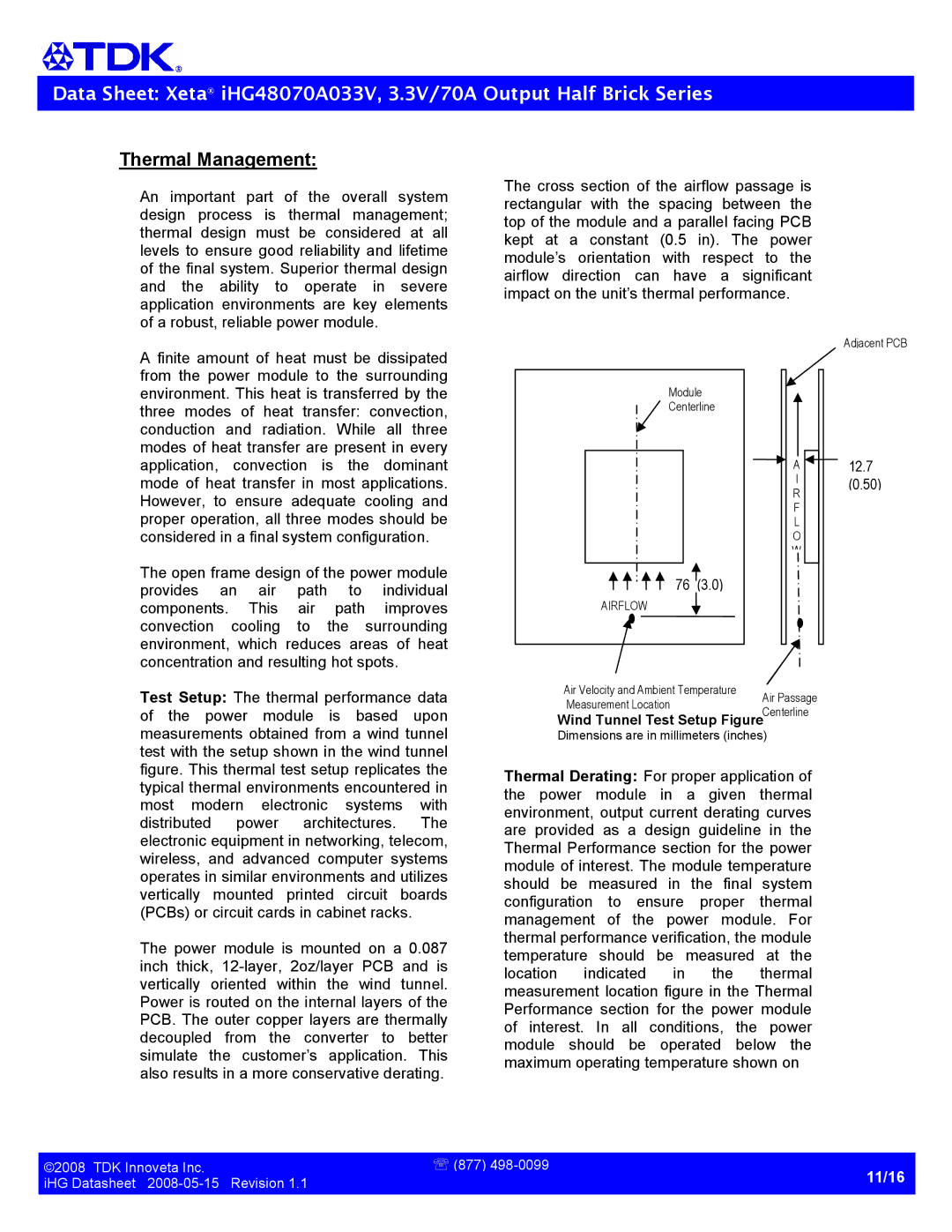
Thecrosssectionoftheairflowpassageis rectangular with the spacing between the topofthemoduleandaparallelfacingPCB kept at a constant (0.5 in). The power module’s orientation with respect to the airflow direction can have a significant impactontheunit’sthermalperformance.
Afiniteamountof heatmustbe dissipated from the power module to the surrounding environment.Thisheatistransferredbythe three modes of heat transfer: convection, conduction and radiation. While all three modesofheattransferarepresentinevery application, convection is the dominant modeofheattransferin mostapplications. However, to ensure adequate cooling and properoperation,allthreemodesshouldbe consideredinafinalsystemconfiguration.
Theopenframedesignofthepowermodule provides an air path to individual components. This air path improves convection cooling to the surrounding environment, which reduces areas of heat concentrationandresultinghotspots.
Module
Centerline
76 (3.0)
AIRFLOW
Adjacent PCB
A12.7
I | (0.50) | |
R | ||
| ||
F |
| |
L |
| |
O |
| |
W |
|
Test Setup:Thethermalperformancedata of the power module is based upon measurementsobtainedfromawindtunnel testwiththesetupshowninthewindtunnel figure.Thisthermaltestsetupreplicatesthe typicalthermalenvironmentsencounteredin most modern electronic systems with distributed power architectures. The electronicequipmentinnetworking,telecom, wireless, and advanced computer systems operatesinsimilarenvironmentsandutilizes vertically mounted printed circuit boards (PCBs)orcircuitcardsincabinetracks.
The power module is mounted on a 0.087 inch thick, 12layer, 2oz/layer PCB and is vertically oriented within the wind tunnel. Powerisroutedontheinternallayersofthe PCB.Theoutercopperlayersarethermally decoupled from the converter to better simulate the customer’s application. This alsoresultsinamoreconservativederating.
Air Velocity and Ambient Temperature
Measurement LocationAir Passage
Wind Tunnel Test Setup FigureCenterline
Dimensionsareinmillimeters(inches)
Thermal Derating: Forproperapplicationof the power module in a given thermal environment,outputcurrentderatingcurves are provided as a design guideline in the ThermalPerformancesectionforthepower moduleofinterest.Themoduletemperature should be measured in the final system configuration to ensure proper thermal management of the power module. For thermalperformanceverification,themodule temperature should be measured at the location indicated in the thermal measurementlocationfigureintheThermal Performance section for the power module of interest. In all conditions, the power module should be operated below the maximumoperatingtemperatureshownon
©2008TDKInnovetaInc. | ℡(877)498 0099 |
iHGDatasheet20080515Revision1.1 | 11/16 |
| |
|
|