Data Sheet: Xeta iHG48070A033V, 3.3V/70A Output Half Brick Series
Input/Output Ripple and Noise Measurements:
Battery
2 1![]()
12uH
1 ![]()
![]()
![]()
![]() 2
2
220uF
esr<0.1
100KHz
2 1![]()
|
| + |
|
| |
Cin |
| Vinput |
|
| |
|
|
|
esr<0.7 |
| |
100KHz | - | |
|
|
|
+
Voutput
-
2 1![]()
1
RLoad
Cext
2
Ground Plane
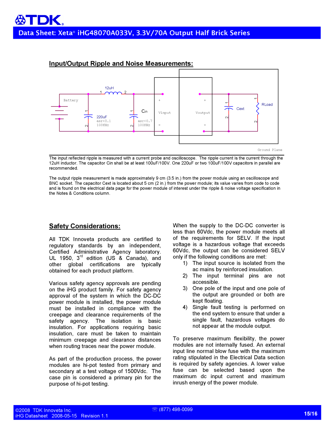
Theinputreflectedrippleismeasuredwithacurre ntprobeandoscilloscope.Theripplecurrentist hecurrentthroughthe 12uHinductor.ThecapacitorCinshallbeatleast 100uF/100V.One220uFortwo100uF/100Vcapacitors inparallelare recommended.
Theoutputripplemeasurementismadeapproximately | 9cm(3.5in.)fromthepowermoduleusinganosci | lloscopeand | |
BNCsocket.ThecapacitorCextislocatedabout5c |
| m(2in.)fromthepowermodule;itsvaluevariesf | romcodetocode |
andisfoundontheelectricaldatapageforthepo | wermoduleofinterestundertheripple&noisevol | tagespecificationin | |
theNotes&Conditionscolumn. |
|
|
|
Safety Considerations:
All TDK Innoveta products are certified to regulatory standards by an independent, Certified Administrative Agency laboratory. UL 1950, 3 rd edition (US & Canada), and other global certifications are typically obtainedforeachproductplatform.
Varioussafetyagencyapprovalsarepending ontheiHGproductfamily.Forsafetyagency approval of the system in which the DCDC powermoduleisinstalled,thepowermodule must be installed in compliance with the creepage and clearance requirements of the safety agency. The isolation is basic insulation. For applications requiring basic insulation, care must be taken to maintain minimum creepage and clearance distances whenroutingtracesnearthepowermodule.
Aspartoftheproductionprocess,thepower modules are hipot tested from primary and secondaryatatestvoltageof1500Vdc. The case pin is considered a primarypin for the purposeofhipottesting.
When the supply to the DCDC converter is lessthan60Vdc,thepowermodulemeetsall of the requirements for SELV. If the input voltage is a hazardous voltage that exceeds 60Vdc, the output can be considered SELV onlyifthefollowingconditionsaremet:
1)Theinputsourceisisolatedfromthe acmainsbyreinforcedinsulation.
2)The input terminal pins are not accessible.
3)Onepoleoftheinputandonepoleof the output are grounded or both are keptfloating.
4)Single fault testing is performed on theendsystemtoensurethatundera single fault, hazardous voltages do notappearatthemoduleoutput.
To preserve maximum flexibility, the power modulesarenotinternallyfused.Anexternal inputlinenormalblowfusewiththemaximum ratingstipulatedintheElectricalDatasection isrequiredbysafetyagencies.Alowervalue fuse can be selected based upon the maximum dc input current and maximum inrushenergyofthepowermodule.
©2008TDKInnovetaInc. | ℡(877)498 0099 |
iHGDatasheet20080515Revision1.1 | 15/16 |
| |
|
|