Data Sheet: Xeta iHG48070A033V, 3.3V/70A Output Half Brick Series
Operating Information:
Output
+/ 0.2 sec time period. An optional feature with latched OVP protection can also be offered. Consult the TDK Innoveta technical supportfordetails.
Thermal Protection: When the power modules exceed the maximum operating temperature, the modules may turnoff to safeguard the power unit against thermal damage. Themodule will auto restart as the unit is cooled below the over temperature threshold. A latched overtemperature protectionoptionisalsoavailable.Consultthe TDKInnovetatechnicalsupportfordetails.
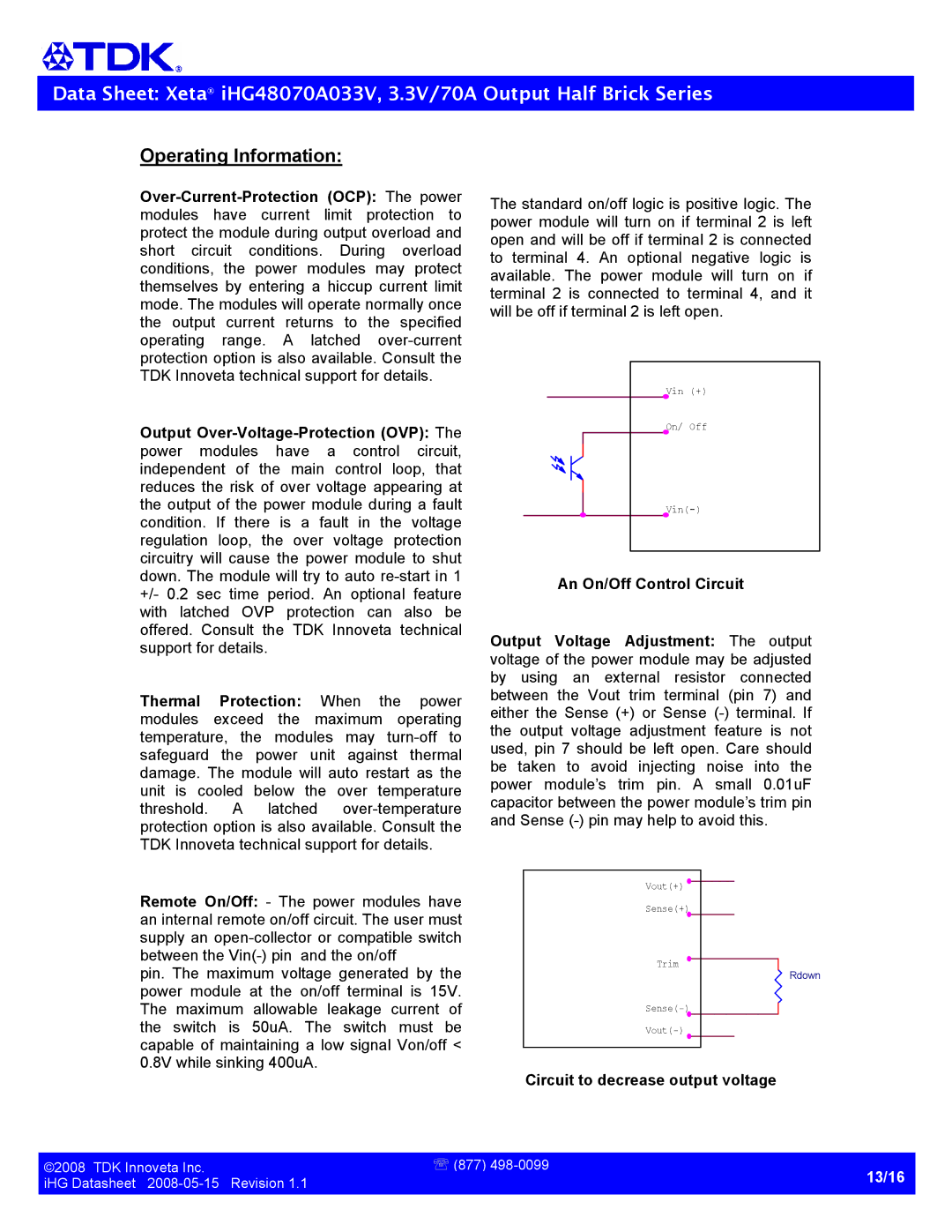
Thestandardon/offlogicispositivelogic.The
powermodulewillturnonifterminal2isleft
openandwillbeoffifterminal2isconnected to terminal 4. An optional negative logic is available. The power module will turn on if terminal 2 is connected to terminal 4, and it willbeoffifterminal2isleftopen.
Vin (+) |
On/ Off |
An On/Off Control Circuit
Output Voltage Adjustment: The output voltageofthepowermodulemaybeadjusted by using an external resistor connected between the Vout trim terminal (pin 7) and either the Sense(+) or Sense() terminal. If the output voltage adjustment feature is not used,pin7shouldbeleftopen. Careshould be taken to avoid injecting noise into the power module’s trim pin. A small 0.01uF capacitorbetweenthepowermodule’strimpin andSense()pinmayhelptoavoidthis.
Remote On/Off: The power modules have aninternalremoteon/offcircuit.Theusermust supplyanopencollectororcompatibleswitch betweentheVin()pinandtheon/off
pin. The maximum voltage generated by the power module at the on/off terminal is 15V. The maximum allowable leakage current of the switch is 50uA. The switch must be capableofmaintainingalowsignalVon/off< 0.8Vwhilesinking400uA.
Vout(+)
Sense(+)
Trim
Rdown
Circuit to decrease output voltage
©2008TDKInnovetaInc. | ℡(877)498 0099 |
iHGDatasheet20080515Revision1.1 | 13/16 |
| |
|
|