Characteristics, Functions, and Applications
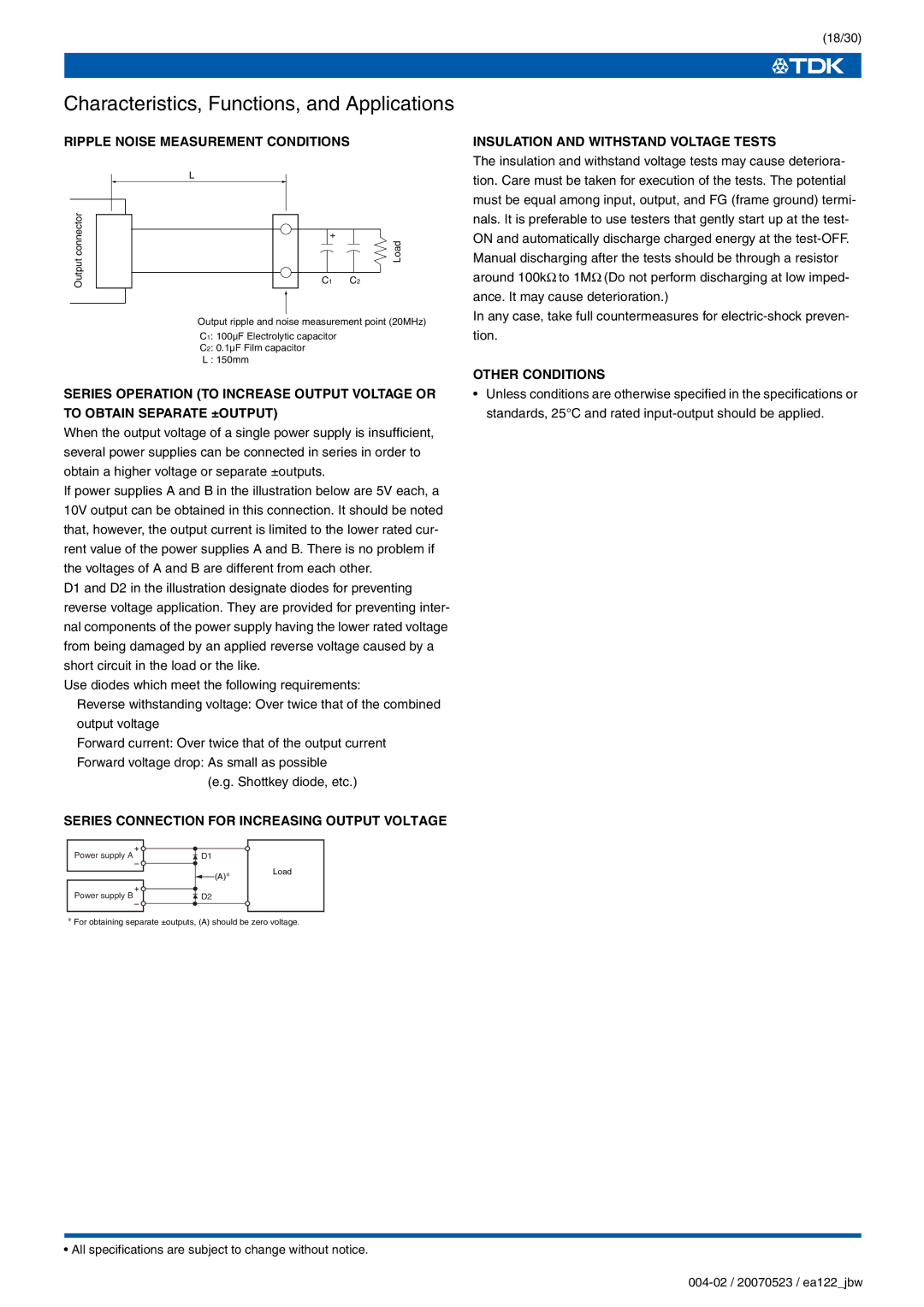
RIPPLE NOISE MEASUREMENT CONDITIONS
L
connectorOutput | + | Load |
|
| |
| C1 | C2 |
Output ripple and noise measurement point (20MHz)
C1: 100µF Electrolytic capacitor
C2: 0.1µF Film capacitor
L : 150mm
SERIES OPERATION (TO INCREASE OUTPUT VOLTAGE OR
TO OBTAIN SEPARATE ±OUTPUT)
When the output voltage of a single power supply is insufficient, several power supplies can be connected in series in order to obtain a higher voltage or separate ±outputs.
If power supplies A and B in the illustration below are 5V each, a 10V output can be obtained in this connection. It should be noted that, however, the output current is limited to the lower rated cur- rent value of the power supplies A and B. There is no problem if the voltages of A and B are different from each other.
D1 and D2 in the illustration designate diodes for preventing reverse voltage application. They are provided for preventing inter- nal components of the power supply having the lower rated voltage from being damaged by an applied reverse voltage caused by a short circuit in the load or the like.
Use diodes which meet the following requirements:
Reverse withstanding voltage: Over twice that of the combined output voltage
Forward current: Over twice that of the output current
Forward voltage drop: As small as possible (e.g. Shottkey diode, etc.)
SERIES CONNECTION FOR INCREASING OUTPUT VOLTAGE
Power supply A | + |
|
D1 |
| |
| – | Load |
| (A)∗ | |
Power supply B | + |
|
D2 |
| |
| – |
|
∗For obtaining separate ±outputs, (A) should be zero voltage.
• All specifications are subject to change without notice.
(18/30)
INSULATION AND WITHSTAND VOLTAGE TESTS
The insulation and withstand voltage tests may cause deteriora- tion. Care must be taken for execution of the tests. The potential must be equal among input, output, and FG (frame ground) termi- nals. It is preferable to use testers that gently start up at the test- ON and automatically discharge charged energy at the
In any case, take full countermeasures for
OTHER CONDITIONS
•Unless conditions are otherwise specified in the specifications or standards, 25°C and rated