4.0INSTALLATION INSTRUCTIONS.
4.1TRANSDUCER
4.1.1Orientation of the Transducer
The transducer may be mounted in any position, as long as the direction of gas flow through the transducer is from “IN” to “OUT” as marked on the transducer base.
4.1.2Mounting the Transducer
There are two
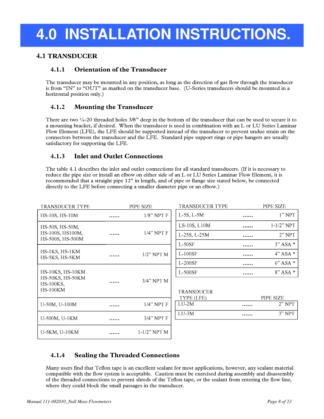
4.1.3Inlet and Outlet Connections
The table 4.1 describes the inlet and outlet connections for all standard transducers. (If it is necessary to reduce the pipe size or install an elbow on either side of an L or LU Series Laminar Flow Element, it is recommended that a straight pipe 12” in length, and of pipe or flange size stated below, be connected directly to the LFE before connecting a smaller diameter pipe or an elbow.)
4.1.4Sealing the Threaded Connections
Many users find that Teflon tape is an excellent sealant for most applications, however, any sealant material compatible with the flow system is acceptable. Caution must be exercised during assembly and disassembly of the threaded connections to prevent shreds of the Teflon tape, or the sealant from entering the flow line, where they could block the small passages in the transducer.
Manual | Page 8 of 23 |