The use of
4.1.5Checking for Leaks
Check the transducer connections for leaks by pressurizing the line to the operating pressure (not to exceed 250 psig except on high pressure models), and applying a diluted soap solution to the pipe joints. Any gas escaping from the pipe joints will cause a continuous stream of bubbles.
4.2FILTERS:
If the flow stream carries particles large enough to block the small passages inside the transducer (approximately .02” ID) a filter should be installed in the flow line of the inlet side of the transducer.
4.3CABLES
4.3.1Description
A standard
4.3.2Cable Length
The cable length can be extended to 25 feet without changing the calibration of the flowmeter by more than
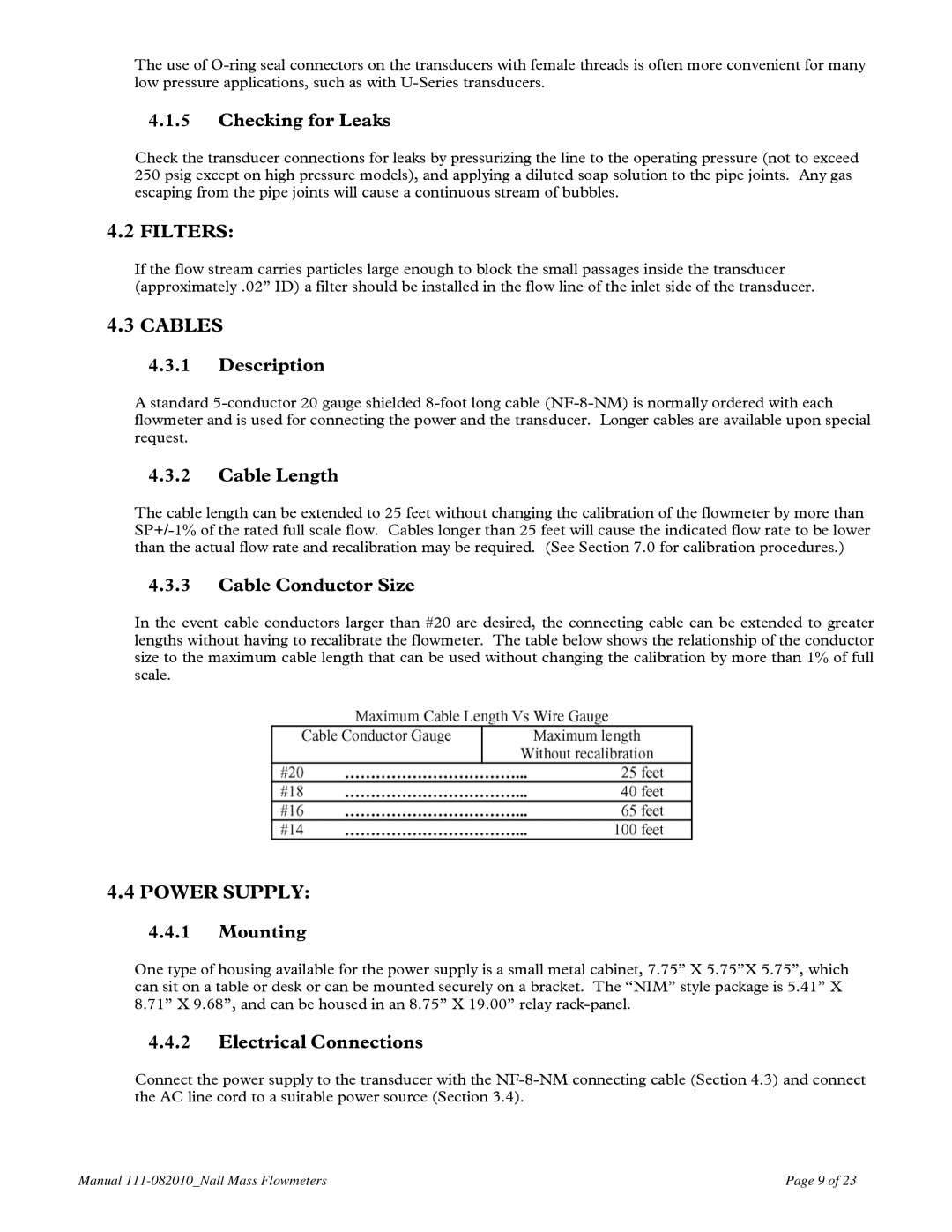
4.3.3Cable Conductor Size
In the event cable conductors larger than #20 are desired, the connecting cable can be extended to greater lengths without having to recalibrate the flowmeter. The table below shows the relationship of the conductor size to the maximum cable length that can be used without changing the calibration by more than 1% of full scale.
4.4POWER SUPPLY:
4.4.1Mounting
One type of housing available for the power supply is a small metal cabinet, 7.75” X 5.75”X 5.75”, which can sit on a table or desk or can be mounted securely on a bracket. The “NIM” style package is 5.41” X 8.71” X 9.68”, and can be housed in an 8.75” X 19.00” relay
4.4.2Electrical Connections
Connect the power supply to the transducer with the
Manual | Page 9 of 23 |