Rack Mount Installation
The
To assemble the rack mount adapters to the
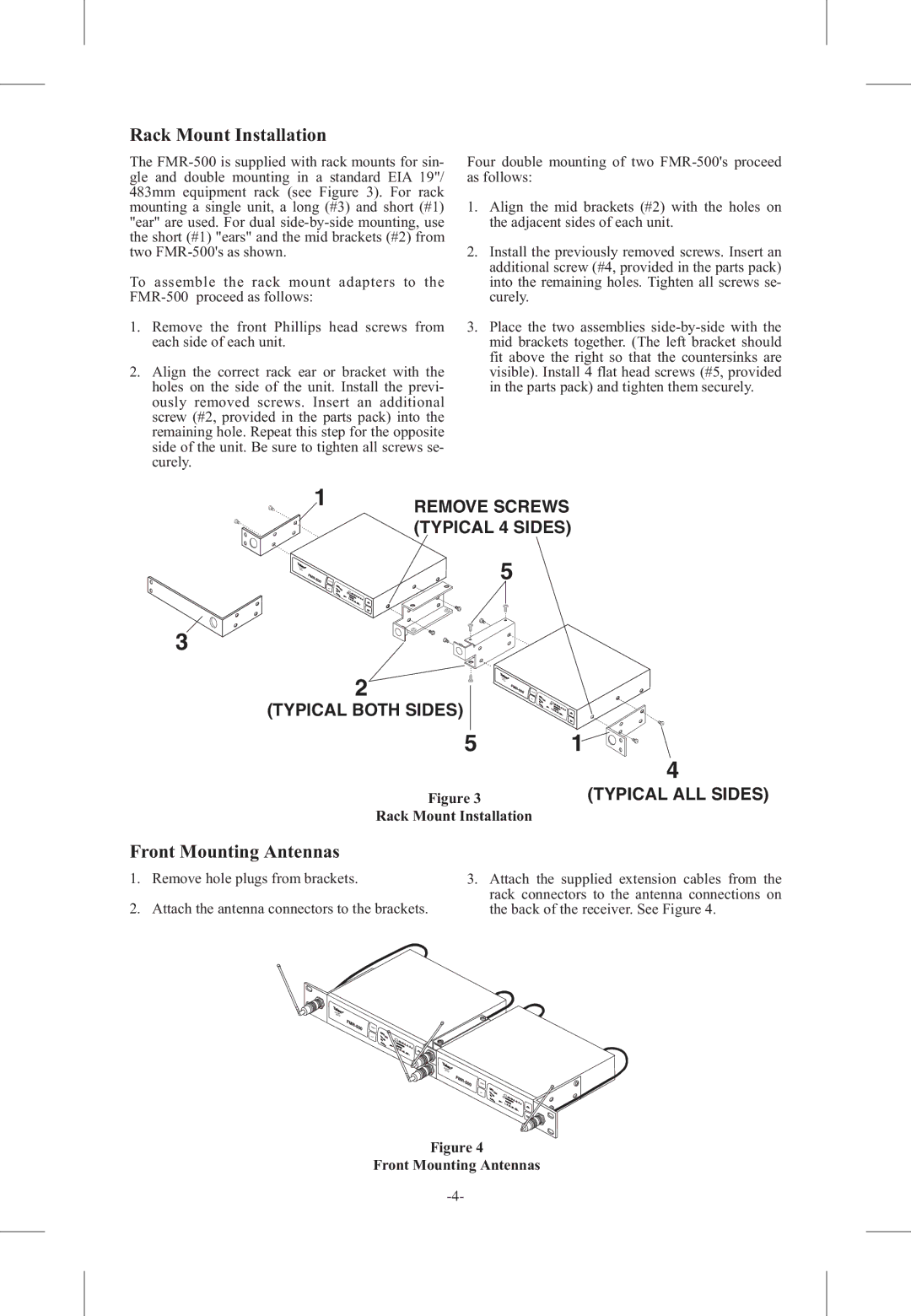
1.Remove the front Phillips head screws from each side of each unit.
2.Align the correct rack ear or bracket with the holes on the side of the unit. Install the previ- ously removed screws. Insert an additional screw (#2, provided in the parts pack) into the remaining hole. Repeat this step for the opposite side of the unit. Be sure to tighten all screws se- curely.
Four double mounting of two
1.Align the mid brackets (#2) with the holes on the adjacent sides of each unit.
2.Install the previously removed screws. Insert an additional screw (#4, provided in the parts pack) into the remaining holes. Tighten all screws se- curely.
3.Place the two assemblies
1 | REMOVE SCREWS |
| |
| (TYPICAL 4 SIDES) |
| 5 |
3
2
(TYPICAL BOTH SIDES)
5 | 1 |
| 4 |
Figure 3 | (TYPICAL ALL SIDES) |
Rack Mount Installation
Front Mounting Antennas
1.Remove hole plugs from brackets.
2.Attach the antenna connectors to the brackets.
3.Attach the supplied extension cables from the rack connectors to the antenna connections on the back of the receiver. See Figure 4.
CLSECAR
AN
![]() power
power
set
CLEA
SCARN
![]() power
power
set
Figure 4