8.Verify reception. With the transmitter and re- ceiver on and matching Group and Channel, the main receiver display should be indicating a RF signal on the bar graph. Speak into the micro- phone and the Audio Meter bar graph should in- dicate audio signal presence. If the level meters do not show reception, make sure the channels are matching and refer to the trouble shooting section.
9.Adjustment of the transmitter audio gain - If necessary The transmitter audio gain is factory set at the middle of the range, which should be suitable for most applications. For loud or soft speakers/singers, a gain adjustment may be nec- essary. Have the speaker or singer use the mi- crophone in a normal performance level voice. The Audio Meter in the main receiver display screen should show peaks around the
To adjust the transmitter gain, gently insert the provided screwdriver (or other 3/32 - 2.5 mm screwdriver) into the adjustment hole above the display screen. Turn lightly until the screw- driver tip goes into the adjustment level control Gently turn counterclockwise until the control stops (the microphone output is at minimum but not off). Slowly turn the gain control up (clock- wise) while speaking/singing into the micro- phone and audiometer shows peaks around
NOTE: Operating with the transmitter audio gain set as high as possible (without distortion or peaks all the way to the right end of the me- ter) will result in the best performance and high- est signal to noise ratio.
10.Test Performance. Go back to Section 3. Re- ceiver Setup and Operation - Step 9 to complete system set up and test.
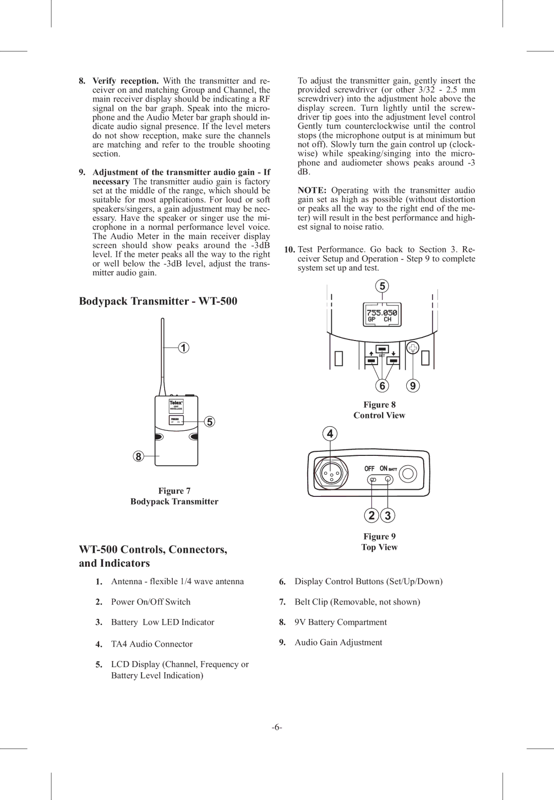
Bodypack Transmitter - WT-500
1
Telex |
|
UHF |
|
WIRELESS |
|
755050 | 5 |
GP CH |
8
Figure 7
Bodypack Transmitter
WT-500 Controls, Connectors, and Indicators
1.Antenna - flexible 1/4 wave antenna
2.Power On/Off Switch
3.Battery Low LED Indicator
4.TA4 Audio Connector
5.LCD Display (Channel, Frequency or Battery Level Indication)
5
SET
6 9
Figure 8
Control View
4
2 3
Figure 9
Top View
6.Display Control Buttons (Set/Up/Down)
7.Belt Clip (Removable, not shown)
8.9V Battery Compartment
9.Audio Gain Adjustment