Procedure | www.ti.com |
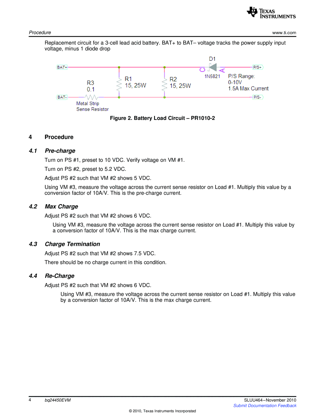
Replacement circuit for a
Figure 2. Battery Load Circuit – PR1010-2
4 Procedure
4.1Pre-charge
Turn on PS #1, preset to 10 VDC. Verify voltage on VM #1. Turn on PS #2, preset to 5.2 VDC.
Adjust PS #2 such that VM #2 shows 5 VDC.
Using VM #3, measure the voltage across the current sense resistor on Load #1. Multiply this value by a conversion factor of 10A/V. This is the
4.2Max Charge
Adjust PS #2 such that VM #2 shows 6 VDC.
Using VM #3, measure the voltage across the current sense resistor on Load #1. Multiply this value by a conversion factor of 10A/V. This is the max charge current.
4.3Charge Termination
Adjust PS #2 such that VM #2 shows 7.5 VDC. There should be no charge current in this condition.
4.4Re-Charge
Adjust PS #2 such that VM #2 shows 6 VDC.
Using VM #3, measure the voltage across the current sense resistor on Load #1. Multiply this value by a conversion factor of 10A/V. This is the max charge current.
4 | bq24450EVM | SLUU464 |
|
| Submit Documentation Feedback |
© 2010, Texas Instruments Incorporated