5 | 4 | 3 | 2 | 1 |
Parts List, Board Layout, and Schematics
D
C
B
A
5
 CTRL_LE
 CTRL_CLK
CTRL_DATA
|
|
| 1 |
|
|
|
|
|
|
|
|
|
|
|
| R62 |
|
|
|
|
|
|
|
|
|
|
|
| 100 | 1 |
|
|
|
|
|
|
|
|
|
|
|
| R63 |
|
|
|
|
|
|
| |
|
|
| 2 |
|
|
|
|
|
|
|
| |
|
|
|
| 100 |
|
|
|
|
|
|
| |
|
|
|
|
|
|
|
|
|
|
|
| |
|
|
|
| 2 |
|
|
|
| VCC |
|
|
|
C 69 | 10p |
|
|
|
| R64 | 100K |
|
|
| ||
|
|
|
|
|
|
|
| |||||
1 |
| 2 |
|
|
| 2 |
| 1 |
|
|
|
|
|
|
|
|
| 1 |
| R 66 100K |
|
|
| ||
|
|
|
|
|
|
|
|
|
| |||
1 |
| 2 |
|
|
|
| 2 | 1 |
|
|
|
|
C 70 | 10p |
|
| R65 |
| R 67 100K |
|
|
| |||
|
| 1 | 2 |
| 2 | 100 | 2 |
| 1 |
|
|
|
|
| C 71 | 10p |
|
|
|
|
|
|
|
| |
GND |
|
|
|
|
|
|
| C72100n | VCC |
| ||
|
|
|
|
|
|
| 1 | 2 |
|
|
| |
|
|
|
|
|
|
|
| 1 | 2 |
|
| VCC |
|
|
|
|
|
|
| GND | C73 |
|
| ||
|
|
|
|
|
|
|
|
|
| |||
|
|
|
|
|
|
|
| 100P |
|
|
| |
|
|
|
|
|
|
| 1 | 1OE | VCC | 14 | R 68 | 10K |
|
|
|
|
|
| LE | 2 | 1A | 4OE | 132 |
| 1 |
|
|
|
|
|
| 3 | 1Y | 4A | 12 |
|
| |
|
|
|
|
|
|
| 4 | 2OE | 4Y | 11 |
|
|
|
|
|
|
|
| CLK | 5 | 2A | 3OE | 10 | GND | |
|
|
|
|
|
| 6 | 9 | |||||
|
|
|
|
|
|
| 7 | 2Y | 3A | 8 |
| DATA |
|
|
|
|
|
|
| GND | 3Y |
| |||
|
|
|
|
|
| GND | SN74LV125U3 |
|
| |||
|
|
|
|
|
|
|
|
|
|
| ||
| 1 | SPI_DATA | 1 | J30 | 14 |
|
|
| VCC | |||
| 2 | 15 |
|
|
| |||||||
J31 | 2 |
| SPI_CLK |
| 3 |
| 16 |
|
|
| 10KR69 | |
| 3 |
| SPI_LE | 4 |
| 17 |
|
|
| |||
HDR4 | 4 |
|
|
|
| 5 |
| 18 |
|
| 1 | 2 |
|
|
|
|
| 6 |
| 19 |
|
|
|
| |
|
|
| GND |
| 7 |
| 20 |
|
|
|
| |
|
|
|
| 8 |
| 21 | GND |
|
|
| ||
|
|
|
|
|
| 9 |
| 22 |
|
|
| |
|
|
|
|
|
| 10 |
| 23 |
|
|
|
|
|
|
|
|
|
| 11 |
| 24 |
|
|
|
|
|
|
|
|
|
| 12 |
| 25 |
|
|
|
|
|
|
|
|
|
| 13 |
| 26 |
|
|
|
|
|
|
|
|
|
|
|
| 27 |
|
|
|
|
PARALLEL PORTGND
4 | 3 |
2
|
|
|
|
|
|
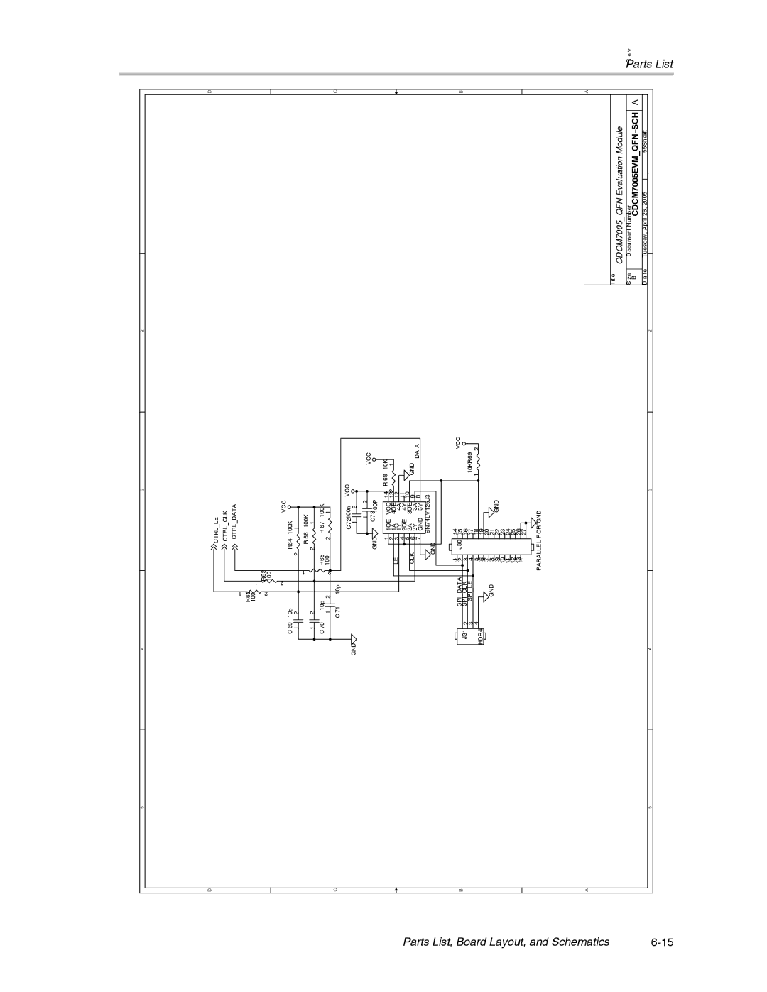
Title | CDCM7005_QFN Evaluation Module |
| |||
|
| ||||
Size | Document Number |
|
| A | |
|
| ||||
B |
| CDCM7005EVM_QFN−SCH | |||
D a te: | Tuesday, April 26, 2005 |
| 55Sheetof |
| |
|
|
|
| 1 |
|
D
C
B
A
R e v PartsList