EVM Operation | www.ti.com |
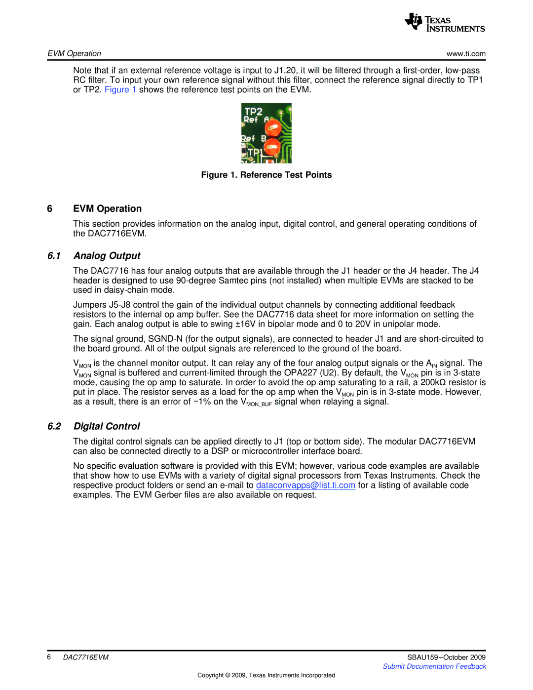
Note that if an external reference voltage is input to J1.20, it will be filtered through a
Figure 1. Reference Test Points
6EVM Operation
This section provides information on the analog input, digital control, and general operating conditions of the DAC7716EVM.
6.1Analog Output
The DAC7716 has four analog outputs that are available through the J1 header or the J4 header. The J4 header is designed to use
Jumpers
The signal ground,
VMON is the channel monitor output. It can relay any of the four analog output signals or the AIN signal. The VMON signal is buffered and
put in place. The resistor serves as a load for the op amp when the VMON pin is in
6.2Digital Control
The digital control signals can be applied directly to J1 (top or bottom side). The modular DAC7716EVM can also be connected directly to a DSP or microcontroller interface board.
No specific evaluation software is provided with this EVM; however, various code examples are available that show how to use EVMs with a variety of digital signal processors from Texas Instruments. Check the respective product folders or send an
6 DAC7716EVM | SBAU159 |
| Submit Documentation Feedback |
Copyright © 2009, Texas Instruments Incorporated