Schematics and Layout | www.ti.com |
Switch S1 allows the user to pull down four control signals to ground. LDAC, Uni/Bip B, RST, and Uni/Bip A can be pulled low using the switch. By default, switch position S1.1 is open, causing LDAC to be connected to ground. Switches S1.2 and S1.4 are open to
Figure 3. Default Settings for Switch S1 (LDAC Low)
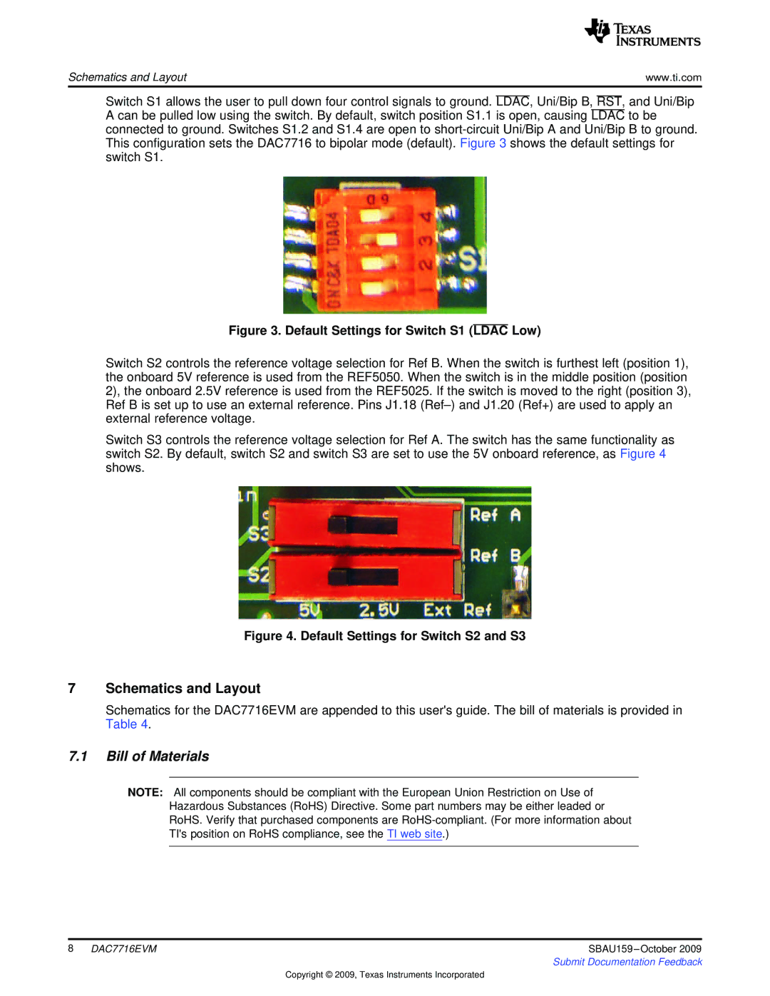
Switch S2 controls the reference voltage selection for Ref B. When the switch is furthest left (position 1), the onboard 5V reference is used from the REF5050. When the switch is in the middle position (position 2), the onboard 2.5V reference is used from the REF5025. If the switch is moved to the right (position 3), Ref B is set up to use an external reference. Pins J1.18
Switch S3 controls the reference voltage selection for Ref A. The switch has the same functionality as switch S2. By default, switch S2 and switch S3 are set to use the 5V onboard reference, as Figure 4 shows.
Figure 4. Default Settings for Switch S2 and S3
7Schematics and Layout
Schematics for the DAC7716EVM are appended to this user'sguide. The bill of materials is provided in Table 4.
7.1Bill of Materials
NOTE: All components should be compliant with the European Union Restriction on Use of Hazardous Substances (RoHS) Directive. Some part numbers may be either leaded or RoHS. Verify that purchased components are
8 DAC7716EVM | SBAU159 |
| Submit Documentation Feedback |
Copyright © 2009, Texas Instruments Incorporated