www.ti.com
EVM Operation
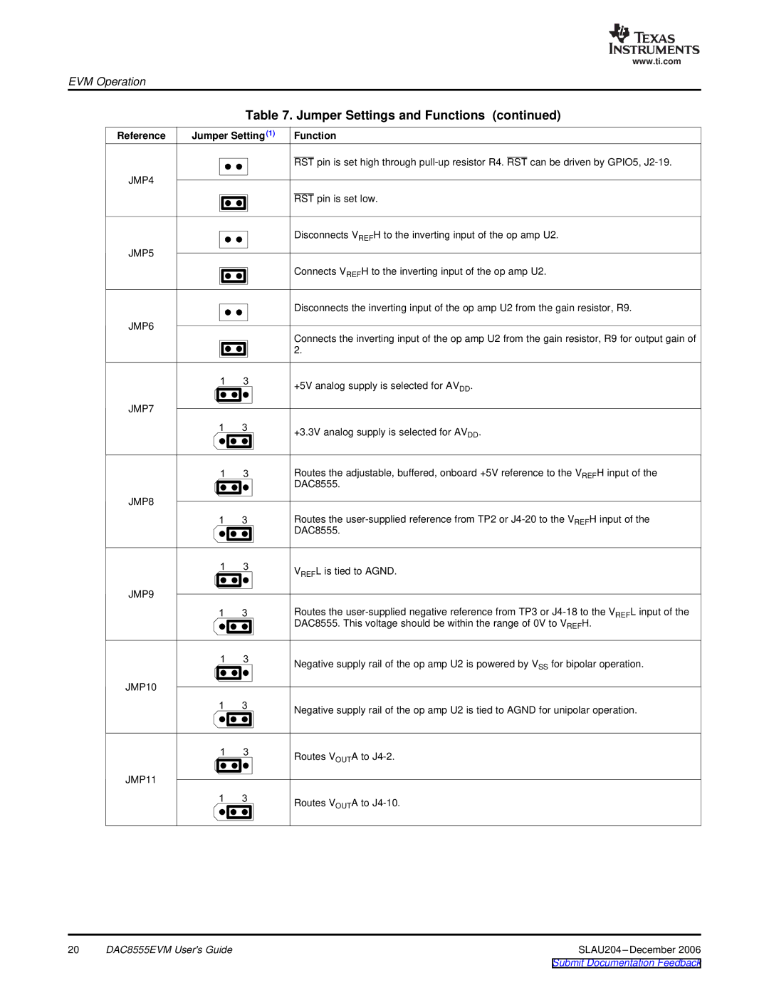
Table 7. Jumper Settings and Functions (continued)
Reference | Jumper Setting (1) |
JMP4
JMP5
JMP6
1 3
JMP7
1 3
1 3
JMP8
1 3
1 3
JMP9
1 3
1 3
JMP10
1 3
1 3
JMP11
1 3
 Function
RST pin is set high through
RST pin is set low.
Disconnects VREFH to the inverting input of the op amp U2.
Connects VREFH to the inverting input of the op amp U2.
Disconnects the inverting input of the op amp U2 from the gain resistor, R9.
Connects the inverting input of the op amp U2 from the gain resistor, R9 for output gain of 2.
+5V analog supply is selected for AVDD.
+3.3V analog supply is selected for AVDD.
Routes the adjustable, buffered, onboard +5V reference to the VREFH input of the DAC8555.
Routes the
VREFL is tied to AGND.
Routes the
Negative supply rail of the op amp U2 is powered by VSS for bipolar operation.
Negative supply rail of the op amp U2 is tied to AGND for unipolar operation.
Routes VOUTA to
Routes VOUTA to
20 | DAC8555EVM User's Guide | SLAU204 |
|
| Submit Documentation Feedback |