SLUU186 − March 2004
6.3Output Ripple and Transient Response
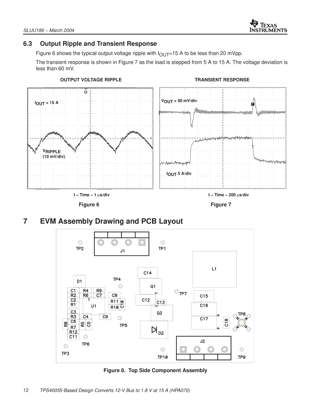
Figure 6 shows the typical output voltage ripple with IOUT=15 A to be less than 20 mVpp.
The transient response is shown in Figure 7 as the load is stepped from 5 A to 15 A. The voltage deviation is less than 60 mV.
OUTPUT VOLTAGE RIPPLE | TRANSIENT RESPONSE |
IOUT = 15 A | VOUT = 50 mV/div |
VRIPPLE (10 mV/div)
| IOUT 5 A/div |
t − Time − 1 ∝s/div | t − Time − 200 ∝s/div |
Figure 6 | Figure 7 |
7 EVM Assembly Drawing and PCB Layout
Figure 8. Top Side Component Assembly
12