|
|
|
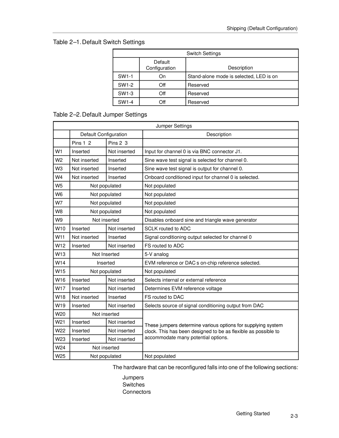
| Shipping (Default Configuration) |
Table |
|
| ||
|
|
|
|
|
|
|
|
| Switch Settings |
|
|
|
|
|
|
|
| Default | Description |
|
|
| Configuration | |
|
|
|
|
|
|
| On | ||
|
|
|
|
|
|
| Off | Reserved | |
|
|
|
|
|
|
| Off | Reserved | |
|
|
|
|
|
|
| Off | Reserved | |
Table 2–2. Default Jumper Settings
|
|
| Jumper Settings | |
|
|
|
| |
| Default Configuration | Description | ||
|
|
|
| |
| Pins | Pins |
| |
|
|
|
| |
W1 | Inserted | Not inserted | Input for channel 0 is via BNC connector J1. | |
|
|
|
| |
W2 | Not inserted | Inserted | Sine wave test signal is selected for channel 0. | |
|
|
|
| |
W3 | Not inserted | Inserted | Sine wave test signal is output for channel 0. | |
|
|
|
| |
W4 | Not inserted | Inserted | Onboard conditioned input for channel 0 is selected. | |
|
|
|
| |
W5 | Not populated | Not populated | ||
|
|
|
| |
W6 | Not populated | Not populated | ||
|
|
|
| |
W7 | Not populated | Not populated | ||
|
|
|
| |
W8 | Not populated | Not populated | ||
|
|
|
| |
W9 | Not inserted | Disables onboard sine and triangle wave generator | ||
|
|
|
| |
W10 | Inserted | Not inserted | SCLK routed to ADC | |
|
|
|
| |
W11 | Not inserted | Inserted | Signal conditioning output selected for channel 0 | |
|
|
|
| |
W12 | Inserted | Not inserted | FS routed to ADC | |
|
|
|
| |
W13 | Not Inserted | |||
|
|
| ||
W14 | Inserted | EVM reference or DAC’s | ||
|
|
| ||
W15 | Not populated | Not populated | ||
|
|
|
| |
W16 | Inserted | Not inserted | Selects internal or external reference | |
|
|
|
| |
W17 | Inserted | Not inserted | Determines EVM reference voltage | |
|
|
|
| |
W18 | Not inserted | Inserted | FS routed to DAC | |
|
|
|
| |
W19 | Inserted | Not inserted | Selects source of signal conditioning output from DAC | |
|
|
|
| |
W20 | Not inserted |
| ||
|
|
|
| |
W21 | Inserted | Not inserted | These jumpers determine various options for supplying system | |
|
|
| ||
W22 | Inserted | Not inserted | ||
clock. This has been designed to be as flexible as possible to | ||||
W23 | Inserted | Not inserted | accommodate many potential options. | |
| ||||
|
|
|
| |
W24 | Not inserted |
| ||
|
|
| ||
W25 | Not populated | Not populated | ||
The hardware that can be reconfigured falls into one of the following sections:
-Jumpers
-Switches
-Connectors
Getting Started | |
|