Host Communication
2.6.2Legacy Connector
J12, J13, and J15 are three 2x20 headers
Two shorting bars are inserted in J12 and J15; these bars permit alternate pins on J13 to be DGND. If the user has complete discretion over signal routing at the host end, it is recommended that the
However, if the
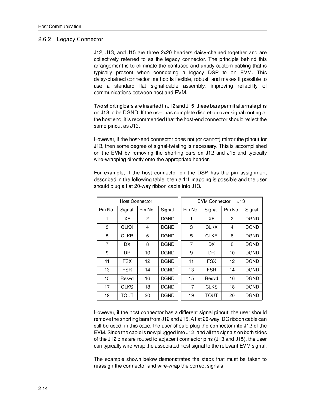
For example, if the host connector on the DSP has the pin assignment described in the following table, then a 1:1 mapping is possible and the user should plug a flat
Host Connector
Pin No. | Signal | Pin No. | Signal |
|
|
|
|
1 | XF | 2 | DGND |
|
|
|
|
3 | CLKX | 4 | DGND |
|
|
|
|
5 | CLKR | 6 | DGND |
|
|
|
|
7 | DX | 8 | DGND |
|
|
|
|
9 | DR | 10 | DGND |
|
|
|
|
11 | FSX | 12 | DGND |
|
|
|
|
13 | FSR | 14 | DGND |
|
|
|
|
15 | Resvd | 16 | DGND |
|
|
|
|
17 | CLKS | 18 | DGND |
|
|
|
|
19 | TOUT | 20 | DGND |
|
|
|
|
EVM Connector – J13
Pin No. | Signal | Pin No. | Signal |
|
|
|
|
1 | XF | 2 | DGND |
|
|
|
|
3 | CLKX | 4 | DGND |
|
|
|
|
5 | CLKR | 6 | DGND |
|
|
|
|
7 | DX | 8 | DGND |
|
|
|
|
9 | DR | 10 | DGND |
|
|
|
|
11 | FSX | 12 | DGND |
|
|
|
|
13 | FSR | 14 | DGND |
|
|
|
|
15 | Resvd | 16 | DGND |
|
|
|
|
17 | CLKS | 18 | DGND |
|
|
|
|
19 | TOUT | 20 | DGND |
|
|
|
|
However, if the host connector has a different signal pinout, the user should remove the shorting bars from J12 and J15. A flat
The example shown below demonstrates the steps that must be taken to reassign the connector and