Jumpers
2.2 Jumpers
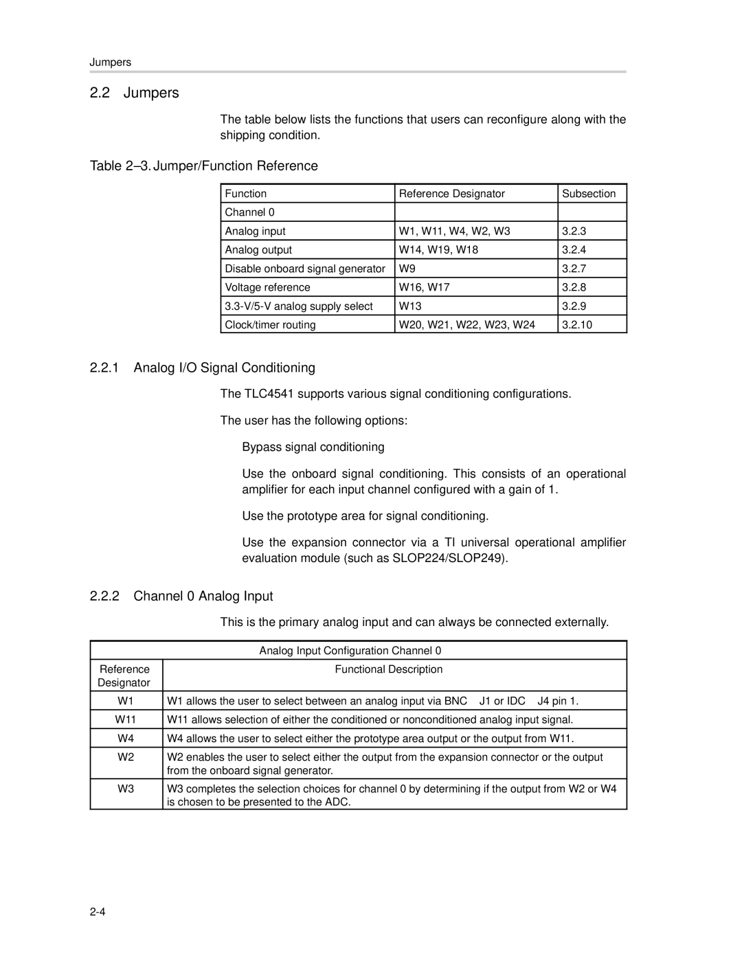
The table below lists the functions that users can reconfigure along with the shipping condition.
Table 2–3. Jumper/Function Reference
Function | Reference Designator | Subsection |
|
|
|
Channel 0 |
|
|
|
|
|
Analog input | W1, W11, W4, W2, W3 | 3.2.3 |
|
|
|
Analog output | W14, W19, W18 | 3.2.4 |
|
|
|
Disable onboard signal generator | W9 | 3.2.7 |
|
|
|
Voltage reference | W16, W17 | 3.2.8 |
|
|
|
W13 | 3.2.9 | |
|
|
|
Clock/timer routing | W20, W21, W22, W23, W24 | 3.2.10 |
2.2.1Analog I/O Signal Conditioning
The TLC4541 supports various signal conditioning configurations.
The user has the following options:
-Bypass signal conditioning
-Use the onboard signal conditioning. This consists of an operational amplifier for each input channel configured with a gain of 1.
-Use the prototype area for signal conditioning.
-Use the expansion connector via a TI universal operational amplifier evaluation module (such as SLOP224/SLOP249).
2.2.2Channel 0 Analog Input
| This is the primary analog input and can always be connected externally. |
|
|
| Analog Input Configuration Channel 0 |
|
|
Reference | Functional Description |
Designator |
|
W1 | W1 allows the user to select between an analog input via BNC – J1 or IDC – J4 pin 1. |
|
|
W11 | W11 allows selection of either the conditioned or nonconditioned analog input signal. |
|
|
W4 | W4 allows the user to select either the prototype area output or the output from W11. |
|
|
W2 | W2 enables the user to select either the output from the expansion connector or the output |
| from the onboard signal generator. |
|
|
W3 | W3 completes the selection choices for channel 0 by determining if the output from W2 or W4 |
| is chosen to be presented to the ADC. |
