www.ti.com | Installation |
1.1TAS5727EVM and MC57xxPSIA Features
•Channel evaluation module design
•
•USB interface
•Standard I2S data input using optical or coaxial inputs
•Analog input through
•Subwoofer connection— the PWM terminal provides the PWM signal and power to an external subwoofer board
•
•Access to control signal gain and data format through
2Installation
This section describes the EVM and software installation.
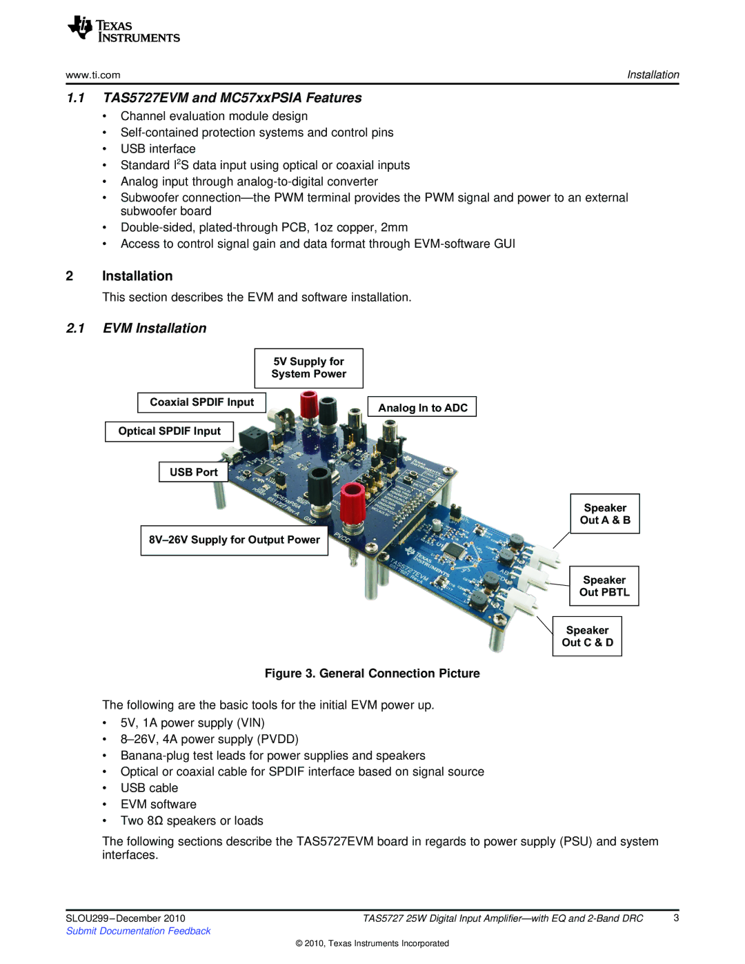
2.1EVM Installation
5V Supply for System Power
Coaxial SPDIF Input
Optical SPDIF Input
USB Port
Analog In to ADC
Speaker
Out A & B
Speaker
Out PBTL
Speaker
Out C & D
Figure 3. General Connection Picture
The following are the basic tools for the initial EVM power up.
•5V, 1A power supply (VIN)
•
•
•Optical or coaxial cable for SPDIF interface based on signal source
•USB cable
•EVM software
•Two 8Ω speakers or loads
The following sections describe the TAS5727EVM board in regards to power supply (PSU) and system interfaces.
SLOU299 | TAS5727 25W Digital Input | 3 |
Submit Documentation Feedback |
|
|
© 2010, Texas Instruments Incorporated
