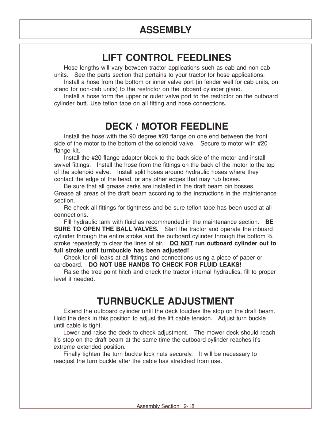
JD 72-7520 specifications
Tiger Products Co., Ltd is renowned for its innovative machinery solutions, and one of its standout offerings is the JD 72-7520 model. This advanced machine is designed to meet the diverse needs of the woodworking and manufacturing industries, providing a range of features that enhance operational efficiency and precision.The JD 72-7520 is characterized by its robust construction, ensuring durability and longevity even in demanding work environments. Built with high-quality materials, this machine can withstand the rigors of continuous use, making it a reliable choice for businesses looking to invest in long-term equipment.
One of the main features of the JD 72-7520 is its powerful motor. This engine drives the machine's operations with superior strength, allowing it to perform heavy-duty tasks effortlessly. The motor's efficiency not only contributes to faster processing times but also results in lower energy consumption, making it an eco-friendly choice for manufacturers.
Technologically, the JD 72-7520 incorporates advanced digital controls that enhance user experience and operational precision. These controls facilitate easy adjustments and settings, enabling operators to fine-tune parameters for different types of materials and desired outcomes. With this level of control, manufacturers can achieve consistent results and maintain high-quality production standards.
Another noteworthy characteristic of the JD 72-7520 is its versatility. Designed to handle various woodworking tasks, the machine can be used for cutting, shaping, and finishing a wide range of materials. This adaptability makes it suitable for different applications, from furniture making to cabinetry and beyond, allowing businesses to expand their service offerings without investing in multiple equipment types.
Moreover, the JD 72-7520 places a strong emphasis on safety features. Enhanced user protection mechanisms are integrated, minimizing the risk of accidents during operation. These include safety guards, emergency stops, and sensors that prevent mishaps, making it a safe working environment for operators.
In summary, the Tiger Products Co., Ltd JD 72-7520 is an extraordinary machine that combines power, efficiency, and safety. Its durable construction, advanced digital controls, versatility, and emphasis on user safety make it a valuable asset for any woodworking or manufacturing business looking to enhance productivity and quality. Whether used in small workshops or large manufacturing facilities, the JD 72-7520 stands out as a top choice in its category.

