PART 2. FUNCTION SELECTION FOR DATA

TRANSMITTING AND RECEIVING UNITS

9.SETTING OF CHANNEL SELECT SWITCH OF TRANSMITTING UNIT (DT-E11) AND WORD SELECT SWITCH OF RECEIVING UNIT (DR-B61)

NOTE

1.Connect the DT-E11 and DR-B61 to Exchange correctly. (Refer to operation manuals of DT-E11 and DR-B61).

2.Set the function select switches (DIP SWITCH) on CP-63 cor- rectly and be sure to enter initial programming and function registration at programming station No.200.

3.Remove the front panel of Data Transmitting Unit
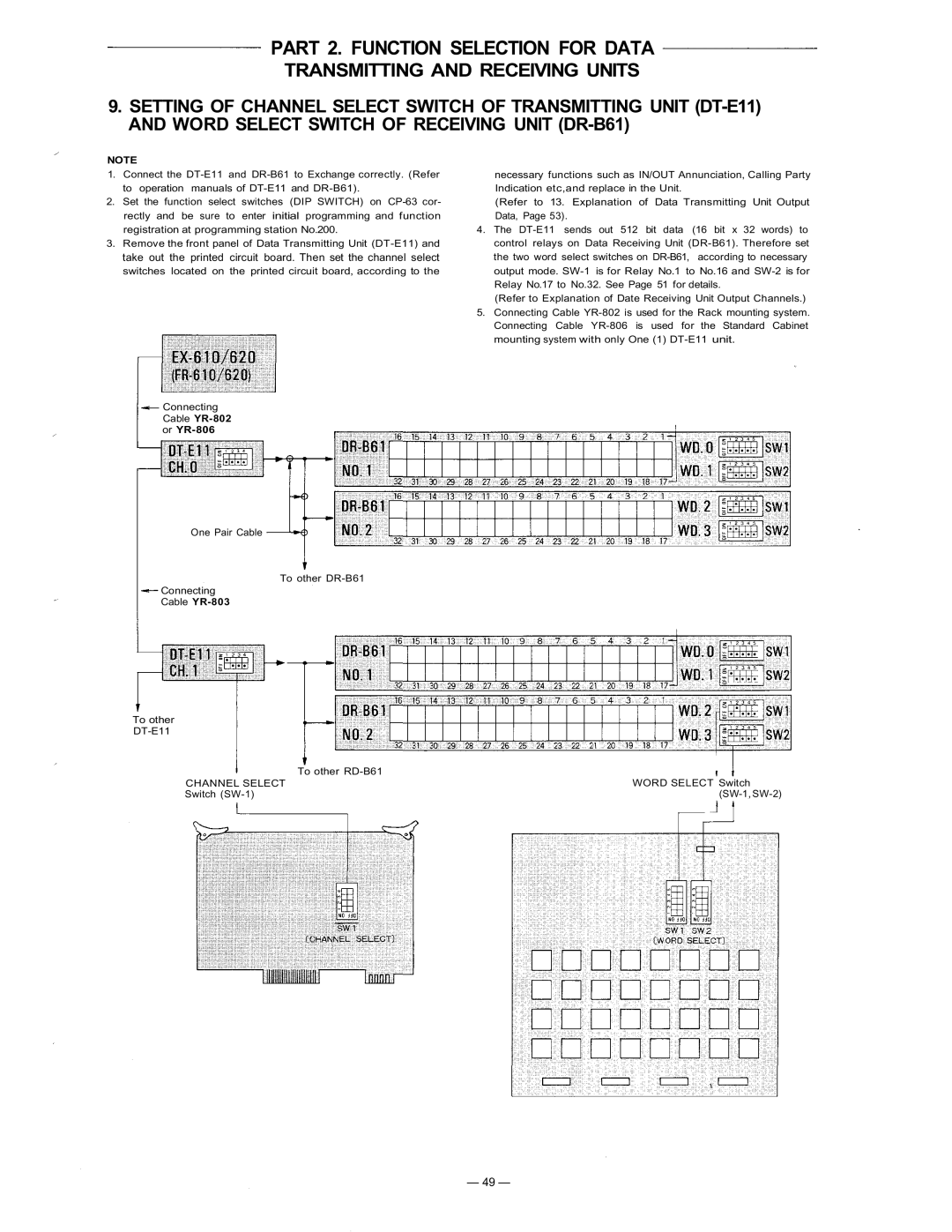
 (DT-E11) and take out the printed circuit board. Then set the channel select switches located on the printed circuit board, according to the

Connecting

Cable YR-802 or YR-806

One Pair Cable

To other DR-B61

Connecting

Cable YR-803

To other

DT-E11

To other RD-B61

CHANNEL SELECT

Switch (SW-1)

necessary functions such as IN/OUT Annunciation, Calling Party Indication etc,and replace in the Unit.

(Refer to 13. Explanation of Data Transmitting Unit Output Data, Page 53).

4.The DT-E11 sends out 512 bit data (16 bit x 32 words) to control relays on Data Receiving Unit (DR-B61). Therefore set the two word select switches on DR-B61, according to necessary output mode. SW-1 is for Relay No.1 to No.16 and SW-2 is for Relay No.17 to No.32. See Page 51 for details.

(Refer to Explanation of Date Receiving Unit Output Channels.)

5.Connecting Cable YR-802 is used for the Rack mounting system. Connecting Cable YR-806 is used for the Standard Cabinet mounting system with only One (1) DT-E11 unit.

WORD SELECT Switch (SW-1, SW-2)

— 49 —

Page 50
Image 50
TOA Electronics CP-63 manual Cable YR-802 or YR-806, Channel Select