GRIDDLES
B.Installation and Electrical Connections
1.Free standing or counter top models
a.CAUTION: Be sure to follow all state and local electrical codes when installing the Toastmaster griddle.
b.Pull out the grease drawer and locate the bag containing the 4” NSF approved, adjustable legs. Models 7224, 7236 and 7324 are all furnished with 6 steel legs. Model A710/A710S has 1 1/4” legs already attached at factory.
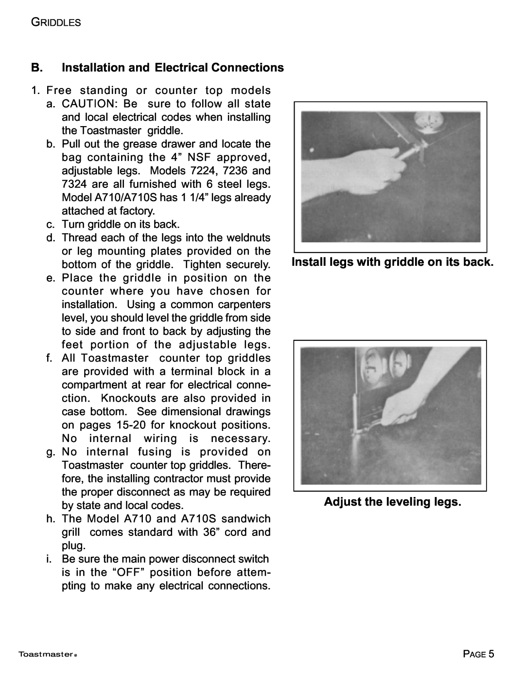
c.Turn griddle on its back.
d.Thread each of the legs into the weldnuts or leg mounting plates provided on the bottom of the griddle. Tighten securely.
e.Place the griddle in position on the counter where you have chosen for installation. Using a common carpenters level, you should level the griddle from side to side and front to back by adjusting the feet portion of the adjustable legs.
f.All Toastmaster counter top griddles
are provided with a terminal block in a compartment at rear for electrical conne- ction. Knockouts are also provided in case bottom. See dimensional drawings on pages
g. No internal fusing is provided on Toastmaster counter top griddles. There- fore, the installing contractor must provide the proper disconnect as may be required by state and local codes.
h. The Model A710 and A710S sandwich grill comes standard with 36” cord and plug.
i.Be sure the main power disconnect switch is in the “OFF” position before attem- pting to make any electrical connections.
Install legs with griddle on its back.
Adjust the leveling legs.
Toastmaster ® | PAGE 5 |