PREINSTALLATION
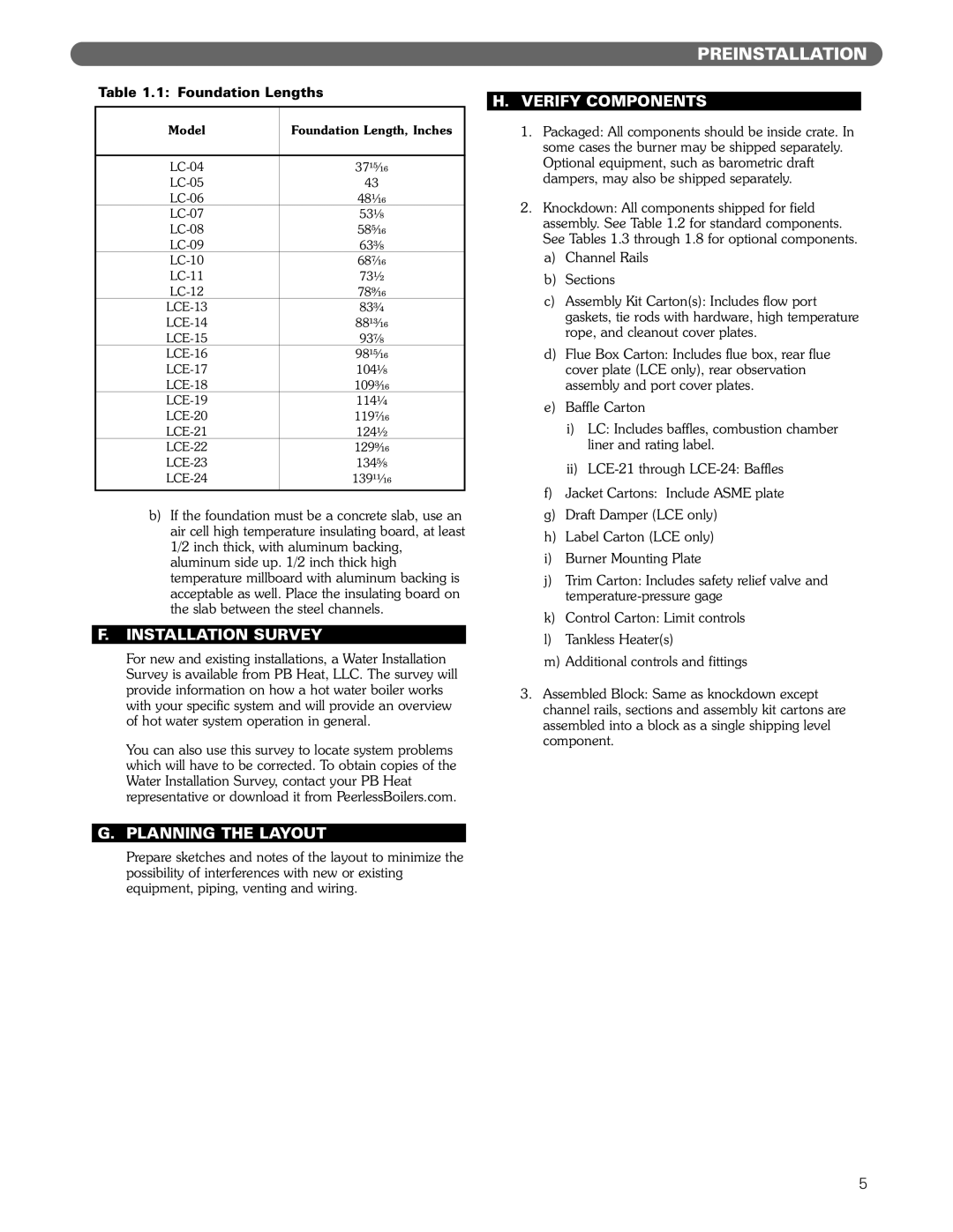
Table 1.1: Foundation Lengths
Model | Foundation Length, Inches |
|
|
37¹⁵⁄₁₆ | |
43 | |
48¹⁄₁₆ | |
53¹⁄₈ | |
58⁵⁄₁₆ | |
63³⁄₈ | |
68⁷⁄₁₆ | |
73¹⁄₂ | |
78⁹⁄₁₆ | |
83³⁄₄ | |
88¹³⁄₁₆ | |
93⁷⁄₈ | |
98¹⁵⁄₁₆ | |
104¹⁄₈ | |
109³⁄₁₆ | |
114¹⁄₄ | |
119⁷⁄₁₆ | |
124¹⁄₂ | |
129⁹⁄₁₆ | |
134⁵⁄₈ | |
139¹¹⁄₁₆ | |
|
|
b)If the foundation must be a concrete slab, use an air cell high temperature insulating board, at least 1/2 inch thick, with aluminum backing, aluminum side up. 1/2 inch thick high temperature millboard with aluminum backing is acceptable as well. Place the insulating board on the slab between the steel channels.
F.INSTALLATION SURVEY
For new and existing installations, a Water Installation Survey is available from PB Heat, LLC. The survey will provide information on how a hot water boiler works with your specific system and will provide an overview of hot water system operation in general.
You can also use this survey to locate system problems which will have to be corrected. To obtain copies of the Water Installation Survey, contact your PB Heat representative or download it from PeerlessBoilers.com.
G.PLANNING THE LAYOUT
Prepare sketches and notes of the layout to minimize the possibility of interferences with new or existing equipment, piping, venting and wiring.
H.VERIFY COMPONENTS
1.Packaged: All components should be inside crate. In some cases the burner may be shipped separately. Optional equipment, such as barometric draft dampers, may also be shipped separately.
2.Knockdown: All components shipped for field assembly. See Table 1.2 for standard components. See Tables 1.3 through 1.8 for optional components.
a)Channel Rails
b)Sections
c)Assembly Kit Carton(s): Includes flow port gaskets, tie rods with hardware, high temperature rope, and cleanout cover plates.
d)Flue Box Carton: Includes flue box, rear flue cover plate (LCE only), rear observation assembly and port cover plates.
e)Baffle Carton
i)LC: Includes baffles, combustion chamber liner and rating label.
ii)
f)Jacket Cartons: Include ASME plate
g)Draft Damper (LCE only)
h)Label Carton (LCE only)
i)Burner Mounting Plate
j)Trim Carton: Includes safety relief valve and
k)Control Carton: Limit controls
l)Tankless Heater(s)
m)Additional controls and fittings
3.Assembled Block: Same as knockdown except channel rails, sections and assembly kit cartons are assembled into a block as a single shipping level component.
5