STARTING THE BOILER
4.Adjust the burner as needed for a CO2 reading of:
a)Oil burners: CO2 approximately 12.5% or 1% less than the level at which the smoke reading goes above a trace on the Bacharach scale.
b)Gas burners: 9% to 10% with CO less than 50 ppm.
c)Inspect all flue gas joints (sections, attachments, breeching and vent) for gas tightness. Remove the jacket panels in order to thoroughly inspect all rope seal joints between the sections.
D.CHECK BOILER CONTROLS
1.Limit and Operating Temperature Controls
a)Lower the setting of each control until the burner shuts down.
2.Low Water Cutoffs
a)Test probe type controls by using the
b)Test float type controls. ASME
3.Follow additional instructions in the Burner Manual for proving the burner component operation.
4.Check all controls to make sure they function correctly.
5.After all controls have been proven, set the Operating and High Limit Temperature Controls to the temperatures desired.
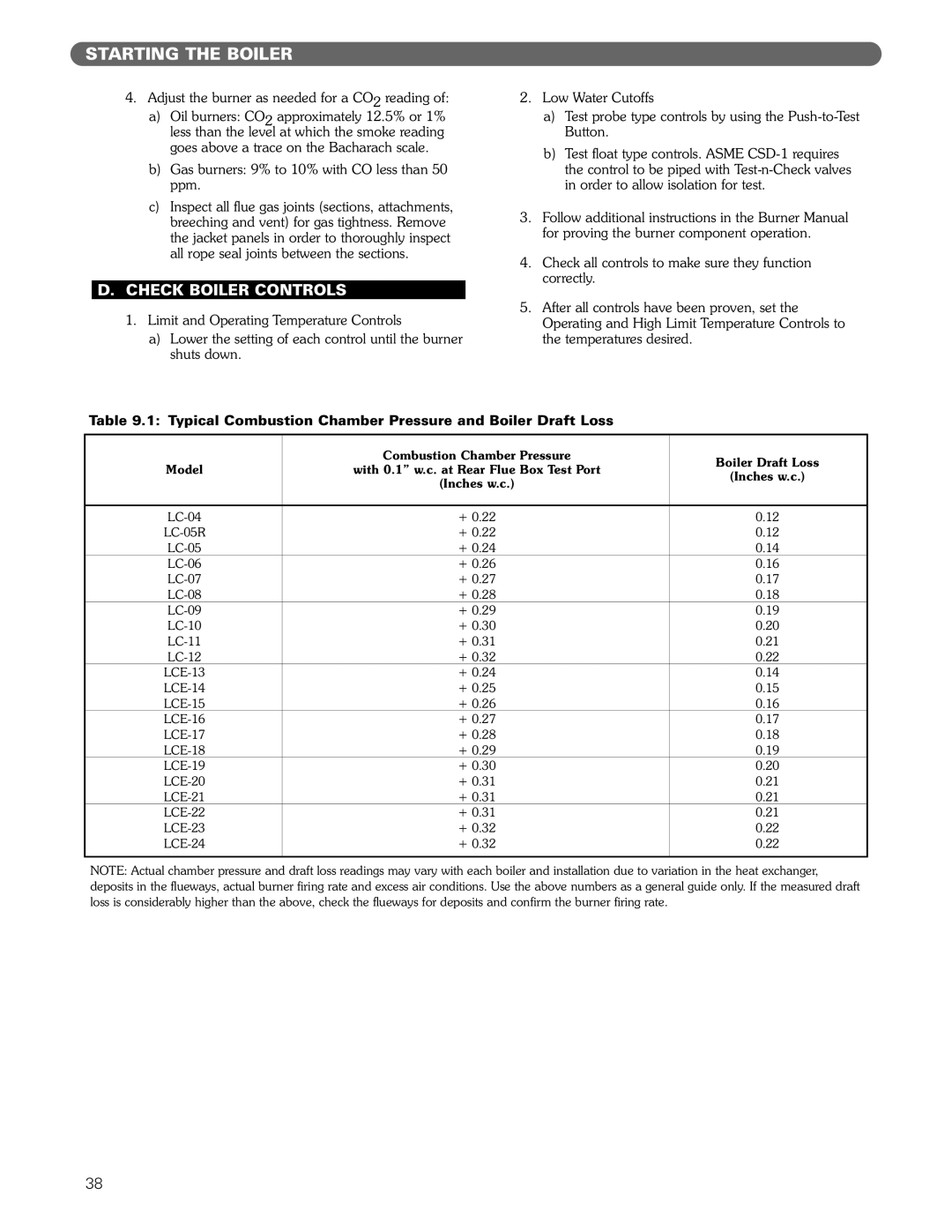
Table 9.1: Typical Combustion Chamber Pressure and Boiler Draft Loss
Model | Combustion Chamber Pressure | Boiler Draft Loss | |
with 0.1” w.c. at Rear Flue Box Test Port | |||
(Inches w.c.) | |||
| (Inches w.c.) | ||
|
| ||
|
|
| |
+ 0.22 | 0.12 | ||
| + 0.22 | 0.12 | |
+ 0.24 | 0.14 | ||
+ 0.26 | 0.16 | ||
+ 0.27 | 0.17 | ||
+ 0.28 | 0.18 | ||
+ 0.29 | 0.19 | ||
+ 0.30 | 0.20 | ||
+ 0.31 | 0.21 | ||
+ 0.32 | 0.22 | ||
+ 0.24 | 0.14 | ||
+ 0.25 | 0.15 | ||
+ 0.26 | 0.16 | ||
+ 0.27 | 0.17 | ||
+ 0.28 | 0.18 | ||
+ 0.29 | 0.19 | ||
+ 0.30 | 0.20 | ||
+ 0.31 | 0.21 | ||
+ 0.31 | 0.21 | ||
+ 0.31 | 0.21 | ||
+ 0.32 | 0.22 | ||
+ 0.32 | 0.22 | ||
|
|
|
NOTE: Actual chamber pressure and draft loss readings may vary with each boiler and installation due to variation in the heat exchanger, deposits in the flueways, actual burner firing rate and excess air conditions. Use the above numbers as a general guide only. If the measured draft loss is considerably higher than the above, check the flueways for deposits and confirm the burner firing rate.
38
