ENGLISH

II. INSTALLATION

IMPORTANT

IT IS THE CUSTOMER’S RESPONSIBILITY TO REPORT ANY CONCEALED OR NON-CONCEALED DAMAGE TO THE FREIGHT COMPANY.

A.Installation Options and Kit Availability

Your hot food server is shipped from the factory with 4” NSF-listed plastic legs, which may be used on single-unit or two-stack installa- tions. The following kits are available from Toastmaster for additional installation options:

P/N ACCHFSC

Casters kit (for 1-4 units)

P/N ACCHFS6

6” legs kit (for 1-4 units)

P/N ACCHFS9

9” legs kit (for 1-4 units)

All hot food server installations REQUIRE the unit(s) to be mounted on legs or casters prior to operation. The allowed installation configu- rations are:


Supplied

Casters

6” legs

9” legs


4” legs

kit

kit

kit


Single unit

YES

YES

YES

YES


Two-stack

YES

YES

YES

YES


Three-stack

NO

YES

YES

YES


Four-stack

NO

YES

YES

YES

CAUTION

STACKING MORE THAN FOUR SERVERS IS NOT PERMITTED.

B.Legs/Casters Assembly

1.To install the supplied 4”/102mm legs (1-2 units only), thread the legs into the four holes on the bottom of the hot food server. An illustration of the server with the supplied legs installed is shown on the cover of this Manual. For a Two-Stack installation, attach the legs to the bottom server only.

2.To install an optional Legs Kit or Casters Kit, refer to the instruc- tions provided with the Kit.

C.Stacking the Hot Food Servers (2-4 units only)

D.Electrical Connection

IMPORTANT

THE ELECTRICAL CONNECTION TO THE HOT FOOD SERVER REQUIRES A CIRCUIT BREAKER/FUSED DISCONNECT. ELEC- TRICAL SPECIFICATIONS ARE LISTED ON THE SERIAL PLATE (SHOWN IN FIGURE 4), AND IN SECTION I OF THIS MANUAL.

CONSULT ALL APPLICABLE NATIONAL AND LOCAL CODES FOR FURTHER ELECTRICAL CONNECTION REQUIREMENTS.

1.Before proceeding with the electrical connection, check the fol- lowing for each hot food server:

a.Check that the electrical supply matches the hot food server’s requirements. Refer to the serial plate (Figure 4) and to the electrical specifications shown in Section 1 of this Manual.

b.Check that the appropriate receptacle is available for the power cord plug.

WARNING

ENSURE THAT BOTH THE CIRCUIT BREAKER/FUSED DIS- CONNECT AND THE POWER ON/OFF (I/O) SWITCH ARE IN THE OFF (“O”) POSITION BEFORE PROCEEDING.

WARNING

ENSURE THAT ANY PACKING MATERIAL HAS BEEN RE- MOVED FROM INSIDE THE CABINET AND FOOD TRAY.

3.Insert (each) power cord plug into its receptacle.

Figure 2

CAUTION

If you have installed the optional Casters Kit, check that the casters are locked before stacking the hot food servers.

Perform the following steps, starting with the server that has legs/ casters installed:

1.

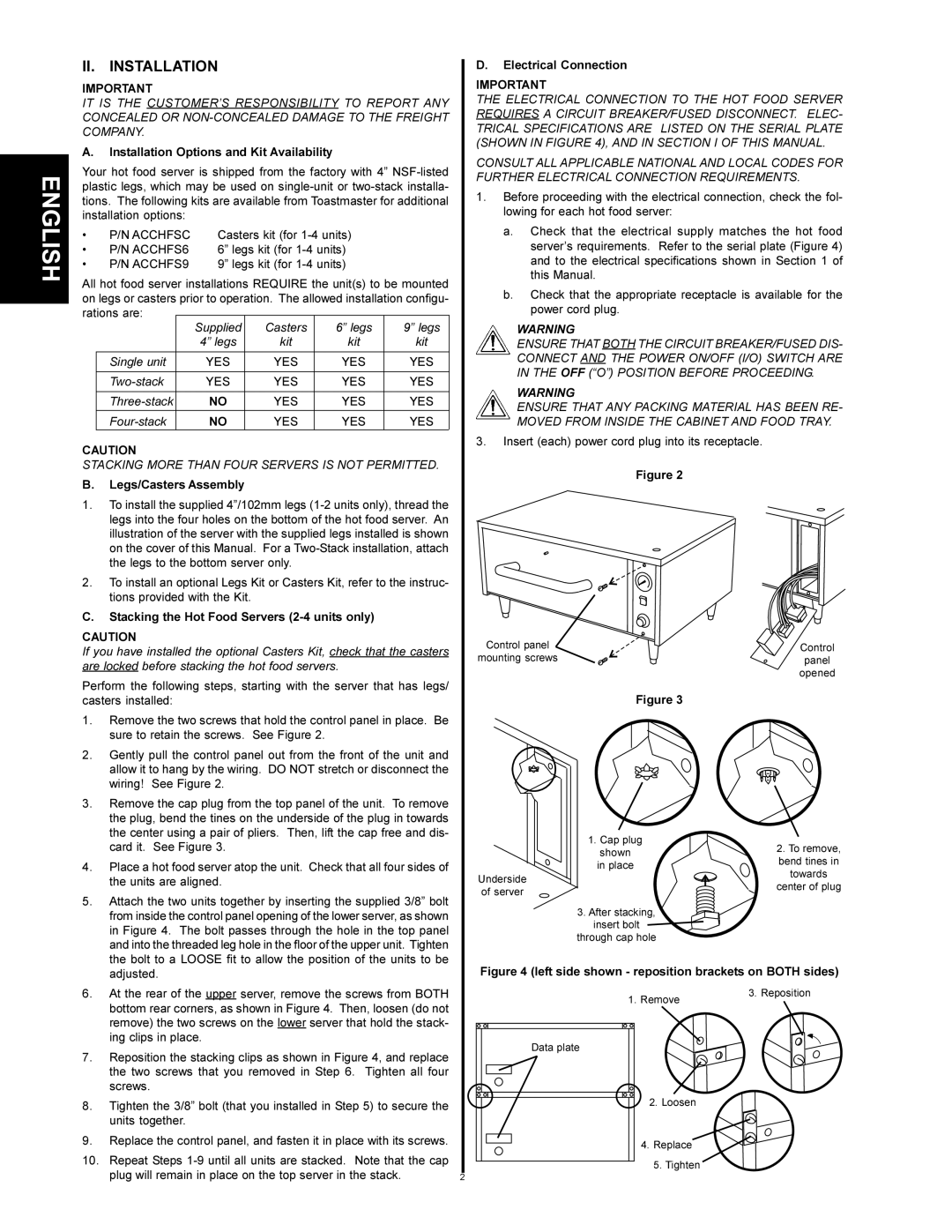
Remove the two screws that hold the control panel in place. Be


sure to retain the screws. See Figure 2.

2.

Gently pull the control panel out from the front of the unit and


allow it to hang by the wiring. DO NOT stretch or disconnect the


wiring! See Figure 2.

3.

Remove the cap plug from the top panel of the unit. To remove


the plug, bend the tines on the underside of the plug in towards


the center using a pair of pliers. Then, lift the cap free and dis-


card it. See Figure 3.

4.

Place a hot food server atop the unit. Check that all four sides of


the units are aligned.

5.

Attach the two units together by inserting the supplied 3/8” bolt


from inside the control panel opening of the lower server, as shown


in Figure 4. The bolt passes through the hole in the top panel


and into the threaded leg hole in the floor of the upper unit. Tighten


the bolt to a LOOSE fit to allow the position of the units to be

Control panel

mounting screws

Figure 3

1. Cap plug

shown

in place

Underside of server

3. After stacking,

insert bolt

through cap hole

Control

panel

opened

2.To remove, bend tines in

towards

center of plug


adjusted.

6.

At the rear of the upper server, remove the screws from BOTH


bottom rear corners, as shown in Figure 4. Then, loosen (do not


remove) the two screws on the lower server that hold the stack-


ing clips in place.

7.

Reposition the stacking clips as shown in Figure 4, and replace


the two screws that you removed in Step 6. Tighten all four


screws.

8.

Tighten the 3/8” bolt (that you installed in Step 5) to secure the


units together.

9.

Replace the control panel, and fasten it in place with its screws.

10.

Repeat Steps 1-9 until all units are stacked. Note that the cap

plug will remain in place on the top server in the stack.

2

Figure 4 (left side shown - reposition brackets on BOTH sides)

1. Remove

3. Reposition


Data plate

2. Loosen

4.Replace 5. Tighten

Page 2
Image 2
Toastmaster HFS72, HFS09 English, II. Installation, Installation Options and Kit Availability, Legs/Casters Assembly

HFS09, HFS72 specifications

Toastmaster HFS09 and HFS72 are two exceptional kitchen appliances designed to make the art of toasting a seamless and enjoyable experience. Both models exemplify Toastmaster's commitment to quality, performance, and innovative features that cater to various cooking needs.

The HFS09 is well-known for its compact design, making it a perfect fit for kitchens with limited counter space. Despite its smaller footprint, this toaster does not compromise on functionality. It boasts a powerful heating element that ensures even browning of bread, bagels, and other toasting needs. A standout feature of the HFS09 is its adjustable browning control, allowing users to choose their preferred toast level, from lightly browned to crispy golden perfection. Additionally, this model is equipped with a convenient cancel button, providing users with the ability to halt toasting at any time.

In contrast, the HFS72 offers a more robust solution for larger households or avid toast lovers. This model features a wide slot design, capable of accommodating thicker slices of artisan bread, bagels, and even pastries. The HFS72 stands out with its dual toasting slots that facilitate simultaneous toasting, appealing to those who value efficiency. Its advanced LED display and user-friendly controls enable precise settings for toasting cycles, ensuring consistent results every time.

Both the HFS09 and HFS72 incorporate advanced technologies that enhance their usability. Notably, they are designed with automatic pop-up features that release the toasted items once they are ready, preventing burning and delivering perfect results. The crumb tray in both models is easily removable, making cleanup simple and hassle-freeā€”an essential factor for any kitchen appliance.

Furthermore, safety is a top priority in the design of these toasters. Each model comes with a safety shut-off feature that activates if the toaster is left unattended for too long, providing peace of mind to users. The exterior of both models is crafted from durable materials, ensuring longevity and resistance to wear and tear.

In summary, the Toastmaster HFS09 and HFS72 present a perfect blend of innovation and convenience, tailored for different user needs. They provide essential features that streamline the toasting process while ensuring safety and ease of use. Whether you are an occasional toasty breakfast lover or a family seeking multiple slices, these models offer an excellent solution to all your toasting requirements.