Communication Interface
Remote Contacts (IBM AS/400)
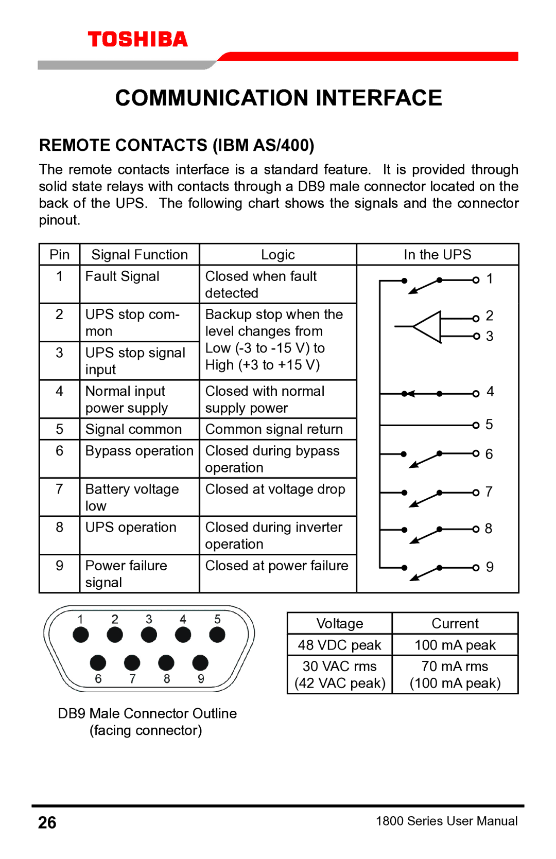
The remote contacts interface is a standard feature. It is provided through solid state relays with contacts through a DB9 male connector located on the back of the UPS. The following chart shows the signals and the connector pinout.
Pin | Signal Function | Logic |
|
|
|
| In the UPS | ||||||||
1 | Fault Signal | Closed when fault |
|
|
|
|
|
|
|
|
|
| 1 | ||
|
| detected |
|
|
|
|
|
|
|
|
|
|
|
| |
2 | UPS stop com- | Backup stop when the |
|
|
|
|
|
|
|
|
| 2 | |||
|
|
|
|
|
|
|
|
| |||||||
|
|
| |||||||||||||
| mon | level changes from |
|
|
|
|
|
|
|
|
|
|
| 3 | |
|
|
|
|
|
|
|
|
|
|
|
| ||||
|
| Low |
|
|
|
|
|
|
|
|
|
| |||
3 | UPS stop signal |
|
|
|
|
|
|
|
|
|
|
|
| ||
| input | High (+3 to +15 V) |
|
|
|
|
|
|
|
|
|
|
|
| |
4 | Normal input | Closed with normal |
|
|
|
|
|
|
|
|
|
| 4 | ||
|
|
|
|
|
|
|
| ||||||||
| power supply | supply power |
|
|
|
|
|
|
|
|
|
| 5 | ||
5 | Signal common | Common signal return |
|
|
|
|
|
|
|
| |||||
|
|
|
|
|
|
|
| ||||||||
|
|
|
|
|
|
|
|
|
|
|
| ||||
6 | Bypass operation | Closed during bypass |
|
|
|
|
|
|
|
|
| 6 | |||
|
|
|
|
| |||||||||||
|
| operation |
|
|
|
|
|
|
|
|
|
|
|
| |
7 | Battery voltage | Closed at voltage drop |
|
|
|
|
|
|
|
|
|
| 7 | ||
|
|
|
|
|
| ||||||||||
| low |
|
|
|
|
|
|
|
|
|
|
|
|
|
|
8 | UPS operation | Closed during inverter |
|
|
|
|
|
|
|
|
|
| 8 | ||
|
|
|
|
|
| ||||||||||
|
| operation |
|
|
|
|
|
|
|
|
|
|
|
| |
9 | Power failure | Closed at power failure |
|
|
|
|
|
|
|
|
|
| 9 | ||
|
|
|
|
|
| ||||||||||
| signal |
|
|
|
|
|
|
|
|
|
|
|
|
|
|
|
|
|
|
|
|
|
|
|
|
|
|
|
|
| |
|
|
| Voltage |
|
|
|
|
| Current | ||||||
|
|
| 48 VDC peak |
|
|
|
|
| 100 mA peak | ||||||
|
|
| 30 VAC rms |
|
|
|
|
| 70 mA rms | ||||||
|
|
| (42 VAC peak) |
|
|
| (100 mA peak) | ||||||||
DB9 Male Connector Outline (facing connector)
26 | 1800 Series User Manual |