RS-232C
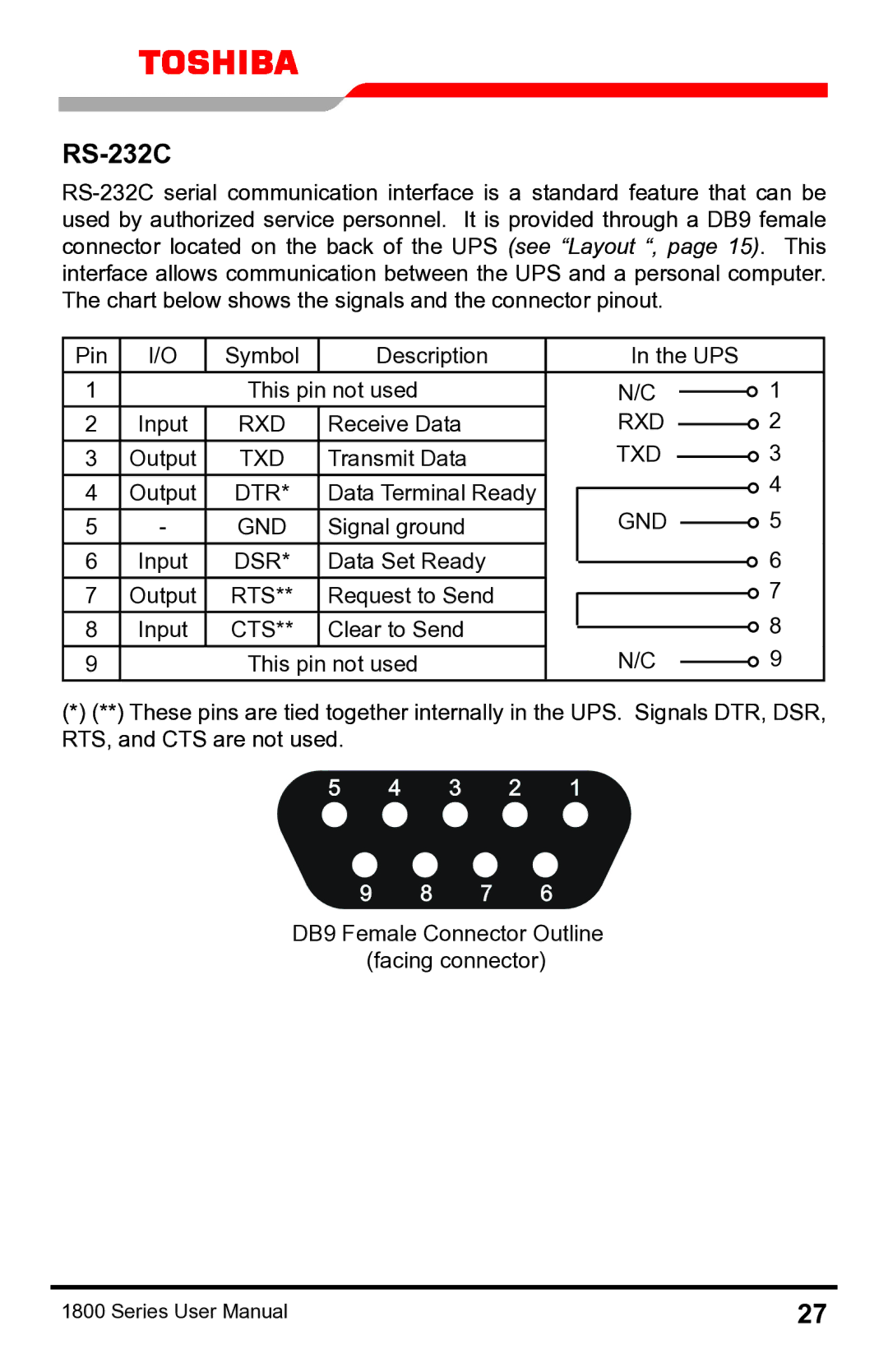
Pin | I/O | Symbol | Description |
| In the UPS |
|
| ||||
1 |
| This pin not used |
| N/C |
|
| 1 | ||||
|
|
| |||||||||
2 | Input | RXD | Receive Data |
| RXD |
|
|
| 2 | ||
|
|
| |||||||||
3 | Output | TXD | Transmit Data |
| TXD |
|
|
| 3 | ||
|
|
| |||||||||
|
|
|
|
|
|
|
|
|
|
| 4 |
4 | Output | DTR* | Data Terminal Ready |
|
|
|
|
|
| ||
|
|
|
|
|
|
| |||||
| GND |
|
| 5 | |||||||
5 | - | GND | Signal ground |
|
|
| |||||
|
| ||||||||||
6 | Input | DSR* | Data Set Ready |
|
|
|
|
|
| 6 | |
|
|
|
|
|
| ||||||
7 | Output | RTS** | Request to Send |
|
|
|
|
|
|
| 7 |
|
|
|
|
|
|
| |||||
8 | Input | CTS** | Clear to Send |
|
|
|
|
|
|
| 8 |
|
|
|
|
|
|
| |||||
9 |
| This pin not used |
| N/C |
|
| 9 | ||||
|
|
| |||||||||
(*)(**) These pins are tied together internally in the UPS. Signals DTR, DSR, RTS, and CTS are not used.
DB9 Female Connector Outline (facing connector)
1800 Series User Manual | 27 |
