Connections and installation
(Continued)
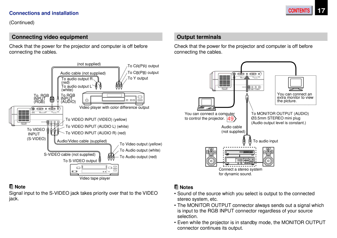
Connecting video equipment
Check that the power for the projector and computer is off before connecting the cables.
CONTENTS | 17 |
Output terminals
Check that the power for the projector and computer is off before connecting the cables.
(not supplied)
Audio cable (not supplied)
To audio output R (red)
To audio output L (white)
To CR(PR) output To CB(PB) output To Y output
CONTROLMONITOR
VIDEO INPUT
RGB | AUDIO |
| RGB INPUT |
L - AUDIO |
To RGB INPUT ![]() (RGB)
(RGB) ![]()
To RGB INPUT (AUDIO)
You can connect an |
extra monitor to view |
the picture. |
Video player with color difference output
RGB | AUDIO | RGB | AUDIO | |
CONTROL | MONITOR OUTPUT |
| RGB INPUT | |
|
| VIDEO INPUT |
| To VIDEO INPUT (VIDEO) (yellow) |
|
|
|
| |
|
| L - AUDIO | ||
To VIDEO |
| To VIDEO INPUT (AUDIO L) (white) | ||
| To VIDEO INPUT (AUDIO R) (red) | |||
INPUT |
|
| ||
|
|
| ||
|
| Audio/Video cable (supplied) | ||
|
|
|
| |
| To Video output (yellow) | |
To Audio output (white) | ||
To Audio output (red) | ||
To | ||
|
Video tape player
![]() Note
Note
Signal input to the
You can connect a computer | To MONITOR OUTPUT (AUDIO) |
to control the projector. 49 | Ø3.5mm STEREO mini plug |
Audio cable | (Audio output level is constant.) |
| |
(not supplied) |
|
To audio input |
Connect a stereo system for dynamic sound.
![]() Notes
Notes
•Sound of the source which you select is output to the connected stereo system, etc.
•The MONITOR OUTPUT connector always sends out a signal which is input to the RGB INPUT connector regardless of your source selection.
•Even while the projector is in standby mode, the MONITOR OUTPUT connector continues its output.