1. OUTLINE
1.3 APPEARANCE AND DIMENSIONS (APPROXIMATE)
1.3 APPEARANCE AND DIMENSIONS (APPROXIMATE)
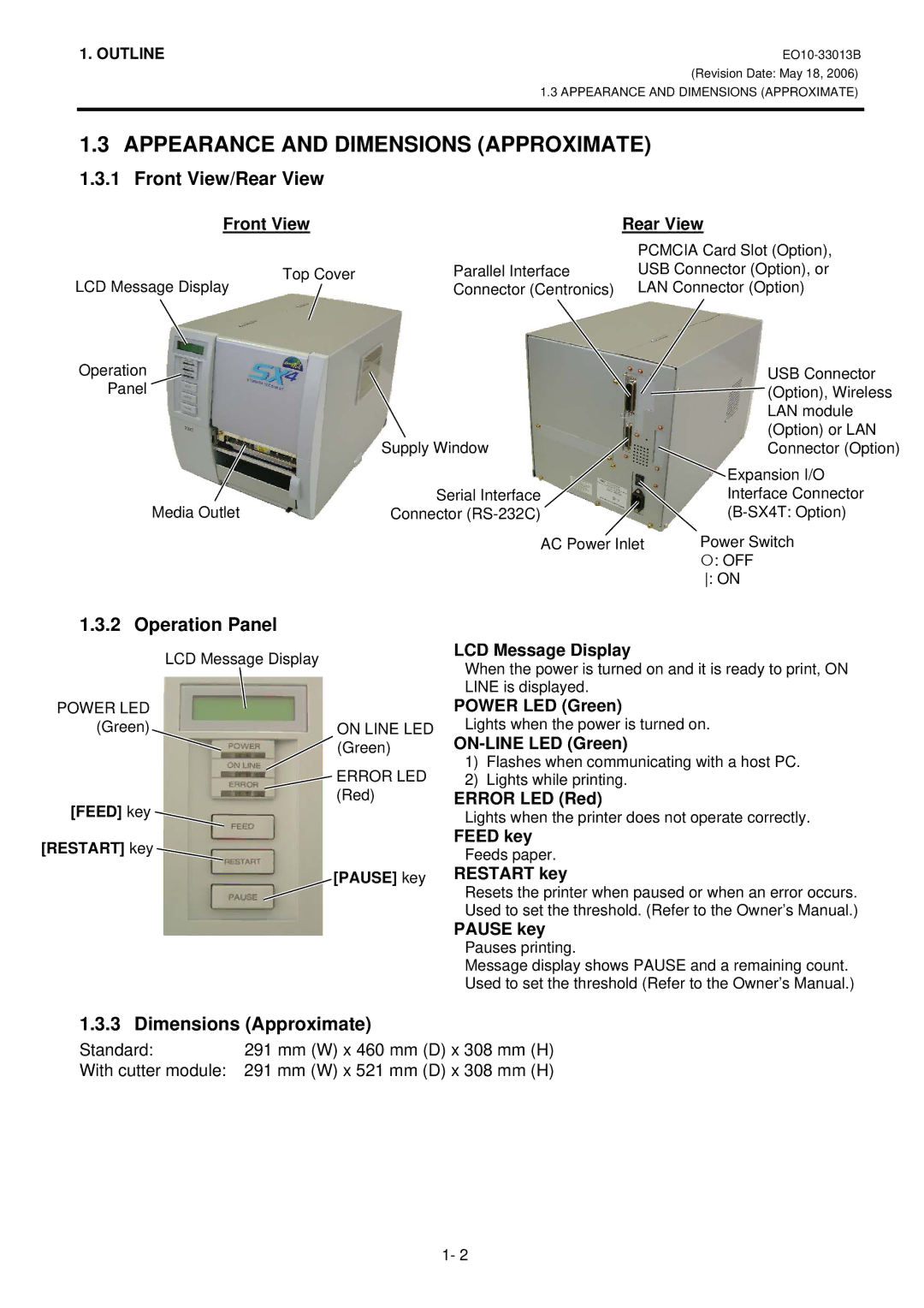
1.3.1 Front View/Rear View
Front View
Rear View |
PCMCIA Card Slot (Option), |
LCD Message Display
Operation
Panel
Top Cover
Parallel Interface | USB Connector (Option), or |
Connector (Centronics) | LAN Connector (Option) |
| USB Connector |
| (Option), Wireless |
| LAN module |
Supply Window | (Option) or LAN |
Connector (Option) | |
| Expansion I/O |
Serial Interface | Interface Connector |
Media Outlet
Connector | ||
|
| |
AC Power Inlet | Power Switch |
|
| {: OFF |
|
| : ON |
|
|
|
|
1.3.2 Operation Panel
LCD Message Display
POWER LED
(Green)ON LINE LED (Green)
ERROR LED (Red)
[FEED] key
[RESTART] key
[PAUSE] key
1.3.3 Dimensions (Approximate)
LCD Message Display
When the power is turned on and it is ready to print, ON LINE is displayed.
POWER LED (Green)
Lights when the power is turned on.
1)Flashes when communicating with a host PC.
2)Lights while printing.
ERROR LED (Red)
Lights when the printer does not operate correctly.
FEED key
Feeds paper.
RESTART key
Resets the printer when paused or when an error occurs. Used to set the threshold. (Refer to the Owner’s Manual.)
PAUSE key
Pauses printing.
Message display shows PAUSE and a remaining count. Used to set the threshold (Refer to the Owner’s Manual.)
Standard: | 291 mm (W) x 460 mm (D) x 308 mm (H) |
With cutter module: | 291 mm (W) x 521 mm (D) x 308 mm (H) |
1- 2