1. OUTLINE
1.5 ELECTRONICS SPECIFICATIONS
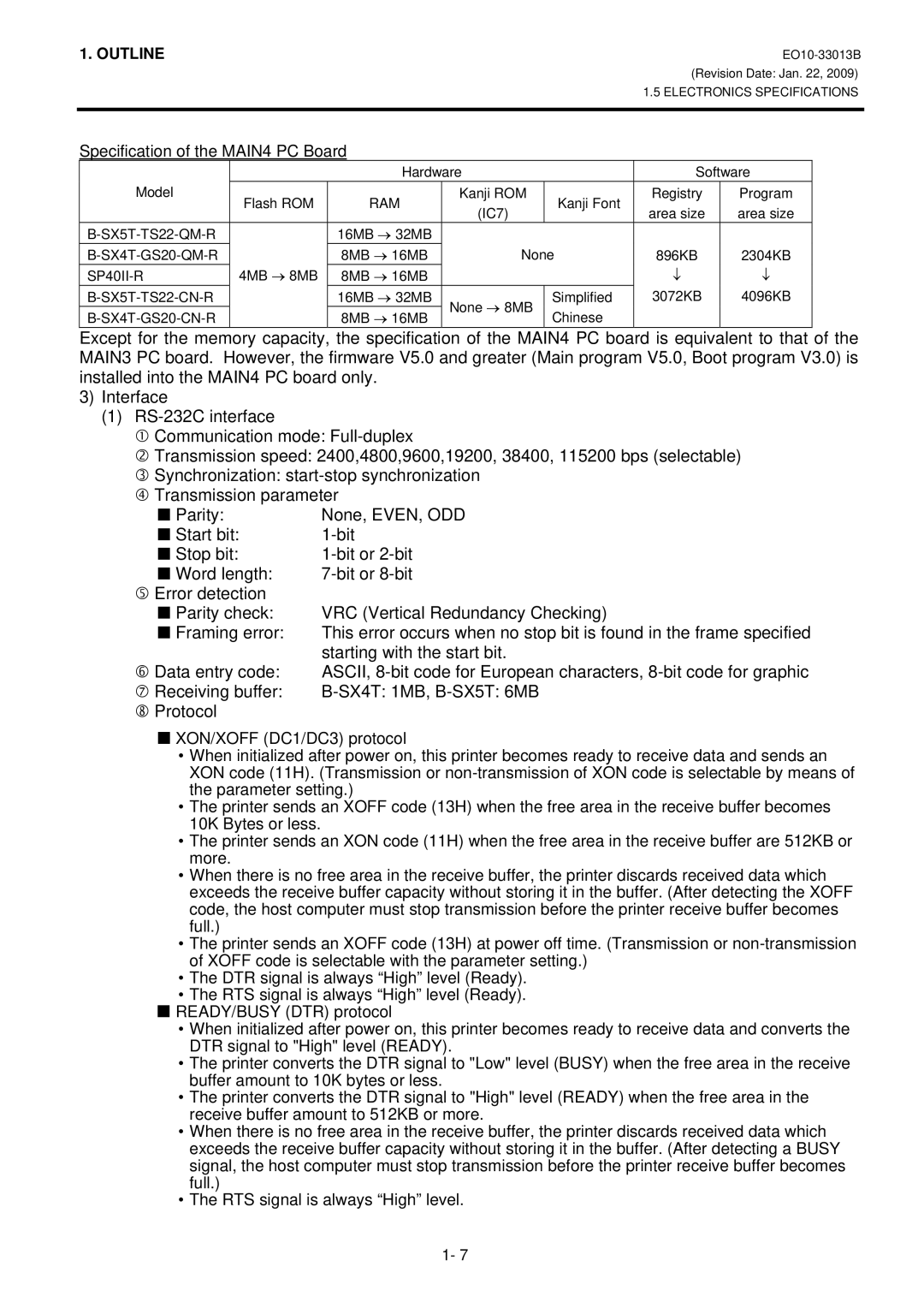
Specification of the MAIN4 PC Board
|
| Hardware |
| Software | ||
Model | Flash ROM | RAM | Kanji ROM | Kanji Font | Registry | Program |
| (IC7) | area size | area size | |||
|
|
|
| |||
| 16MB → 32MB |
|
|
|
| |
| 8MB → 16MB | None | 896KB | 2304KB | ||
4MB → 8MB | 8MB → 16MB |
|
| ↓ | ↓ | |
| 16MB → 32MB | None → 8MB | Simplified | 3072KB | 4096KB | |
| 8MB → 16MB | Chinese |
|
| ||
|
|
|
| |||
Except for the memory capacity, the specification of the MAIN4 PC board is equivalent to that of the MAIN3 PC board. However, the firmware V5.0 and greater (Main program V5.0, Boot program V3.0) is installed into the MAIN4 PC board only.
3)Interface
(1)
c Communication mode:
d Transmission speed: 2400,4800,9600,19200, 38400, 115200 bps (selectable)
e Synchronization:
Parity: | None, EVEN, ODD |
Start bit: | |
Stop bit: | |
Word length: | |
g Error detection |
|
Parity check: | VRC (Vertical Redundancy Checking) |
Framing error: | This error occurs when no stop bit is found in the frame specified |
| starting with the start bit. |
h Data entry code: | ASCII, |
i Receiving buffer: |
jProtocol
XON/XOFF (DC1/DC3) protocol
•When initialized after power on, this printer becomes ready to receive data and sends an XON code (11H). (Transmission or
•The printer sends an XOFF code (13H) when the free area in the receive buffer becomes 10K Bytes or less.
•The printer sends an XON code (11H) when the free area in the receive buffer are 512KB or more.
•When there is no free area in the receive buffer, the printer discards received data which exceeds the receive buffer capacity without storing it in the buffer. (After detecting the XOFF code, the host computer must stop transmission before the printer receive buffer becomes full.)
•The printer sends an XOFF code (13H) at power off time. (Transmission or
•The DTR signal is always “High” level (Ready).
•The RTS signal is always “High” level (Ready).
READY/BUSY (DTR) protocol
•When initialized after power on, this printer becomes ready to receive data and converts the DTR signal to "High" level (READY).
•The printer converts the DTR signal to "Low" level (BUSY) when the free area in the receive buffer amount to 10K bytes or less.
•The printer converts the DTR signal to "High" level (READY) when the free area in the receive buffer amount to 512KB or more.
•When there is no free area in the receive buffer, the printer discards received data which exceeds the receive buffer capacity without storing it in the buffer. (After detecting a BUSY signal, the host computer must stop transmission before the printer receive buffer becomes full.)
•The RTS signal is always “High” level.
1- 7
