RAV-SM1103AT-E1 RAV-SM1403AT-E1
Contents
Original instruction
Explanation of illustrated marks
Explanation of indications
Work undertaken Protective gear worn
Indication Explanation
Description
Confirmation of warning label on the main unit
Precaution for Safety
Undertake the work
Refrigerant used by this air conditioner is the R410A
Properly
Relocation
Explanations given to user
Model names with a rating of 12 kW and below outdoor units
DI series
Pipe Materials
Safety Caution Concerned to New Refrigerant
Copper pipe Piping
Flare nut
General tools Conventional tools can be used
Tools
Digital Inverter
Outdoor Unit
Capacity variation ratio according to temperature
Operation Characteristic Curve
Operation Characteristic Curve Digital Inverter
Cooling Heating
RAV-SM1103AT-E1, RAV-SM1403AT-E1
Construction Views External Views
Model RBC
RBC-TWP30E2, RBC-TWP50E2 Simultaneous Twin
Outdoor unit
RAV-SM1103AT-E1
Wiring Diagram
Specifications of Electric Parts
Refrigerant Piping Installation
Safety During Installation/Servicing
Piping Materials and Joints Used
Copper Pipes
Joints
Flare Processing Procedures and Precautions
Processing of Piping Materials
Flare and flare nut dimensions for R410A
3 Dimensions related to flare processing for R410A / R22
Flare and flare nut dimensions for R22
R410A R22 R410A, R22 Clutch type Wing nut type
Nm kgfm
Flare Connecting Procedures and Precautions
Wrenches available on the market
Required Tools
Recharging of Refrigerant
Flux Reason why flux is necessary
Low temperature brazing filler
Brazing of Pipes
Materials for Brazing Silver brazing filler
Types of flux
Characteristics required for flux
Piping materials for brazing and used brazing filler/flux
Brazing
Basic Conditions Needed to Reuse the Existing Pipe
Instructions for Re-use Piping of R22 or R407C
Restricted Items to Use the Existing Pipes
Branching Pipe for Simultaneous Operation System
YES
Final Installation Checks
Reference outside diameter Wall thickness
Handling of Existing Pipe
CN806
Outline of Main Controls Pulse Modulating Valve PMV control
Discharge temperature release control
Outdoor fan control
Current release control
Cooling fan control
Allocations of fan tap revolutions rpm
Heating fan control
Coil heating control
Normal time
Defective to sensor
Defrost control
Current release value shift control
Current release control value
At normal to At error to Zone
High-pressure switch
Control of compressor case thermo
Start of heating operation
Before troubleshooting
Summary of Troubleshooting
Troubleshooting procedure
Wired remote controller type
Trouble Confirmation of lamp display
Wireless remote controller type
Outline of judgment
Troubleshooting
Lamp indication Check code Cause of trouble occurrence
Others Other than Check Code
Pushing Test button returns the status to the usual display
Contents
Indication
Check Code List Outdoor
Central control indication Remote controller
TCJ
Error mode detected by indoor unit
After
Error mode detected by outdoor unit
After Series
Operation of diagnostic function Judgment and measures
Contents Error Display
Display of the latest error
Diagnostic Procedure for Each Check Code Outdoor Unit
YES
Case thermostat operation E04
F06
Heat exchanger temp. sensor TE error
F13 Heat sink temp. sensor TH error
F12 Suction temp. sensor TS error
F15 Miswiring of heat exchanger sensor TE, TS
H02 Compressor lock
H01 Compressor break down
L10
P03 Discharge temp. error
Power supply error Vdc, High pressure protective operation
High pressure SW system error
P15 Gas leak detection
P07 Heat sink overheat error
Way valve reversal error
Check Code P19 Outdoor Check and troubleshooting LED display
Open valve fully
Single operation check for outdoor fan
Method
Position detection circuit error
TA, TC, TCJ, TE, TS, to sensors Representative value
Temperature sensor
TD, TL sensors Representative value
TA, TC, TCJ, TE, TS, to sensors
Table Inspection of outdoor unit main parts
Parts name Checking procedure
Resistance value
Position
Contents
Calling of Error History
Procedure
Group Control Operation
By feed unit Automatic address judgment
„ Indoor unit power-ON sequence
Initial communication
Usual regular Communication
Refrigerant recovery control
Service switch SW800, SW801 operations
Outdoor Unit
Service switch setting
Case to return the setting to one at shipment from factory
LED display switching Display switching list
Error display
ON, OFF, Slow flashing Once/second
Open PMV Electronic expansion valve fully
Applicable Control of Outdoor unit
Address Setup Procedure
Address Setup
System Configuration
Address Setup & Group Control
Terminology
Only turning on source power supply Automatic completion
Automatic Address Example from Unset Address No miswiring
Standard One outdoor unit Single Twin
Wiring diagram
Remote Controller Wiring
Address Setup Manual setting from remote controller
Single system Simultaneous twin system
Button
Confirmation of Indoor Unit No. Position
To know the position of indoor unit body by address
Maintenance/Check list
Installing the P.C. board
Setting the jumper wires
Removing the P.C. board
Exchange of Compressor
Exchanging Procedure of Compressor Outline
Detachments
Discharge port
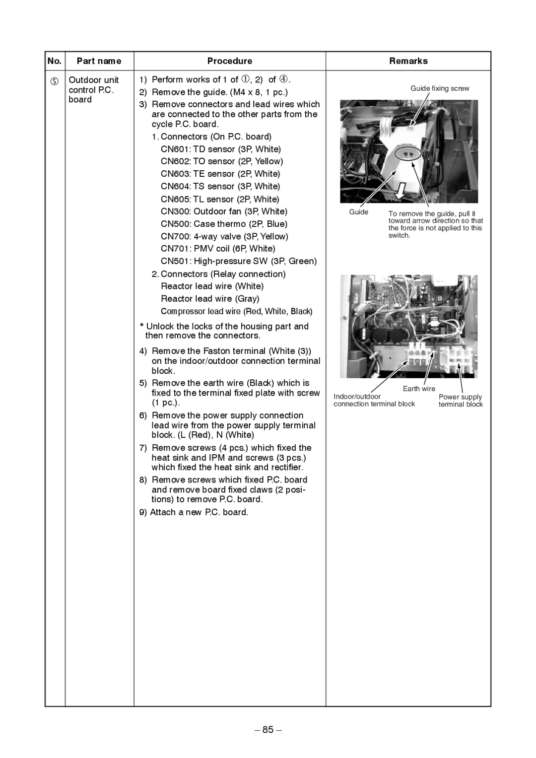
Part name Procedure Remarks
Perform works of 1 of c, 2 of f
Propeller fan
When reconnecting the lead wires to
Pulse Modulating
Product
Exploded Views and Parts List
RAV
Inverter assembly
Toshiba Carrier Corporation