E6581315

„Inverter → Computer

At time of broadcast communication of the binary mode, returning of data is not executed except for the inverter to be returned (inverter number 00H) and when the inverter number is not matched. This is because there will be a risk that the returned data may be deformed.

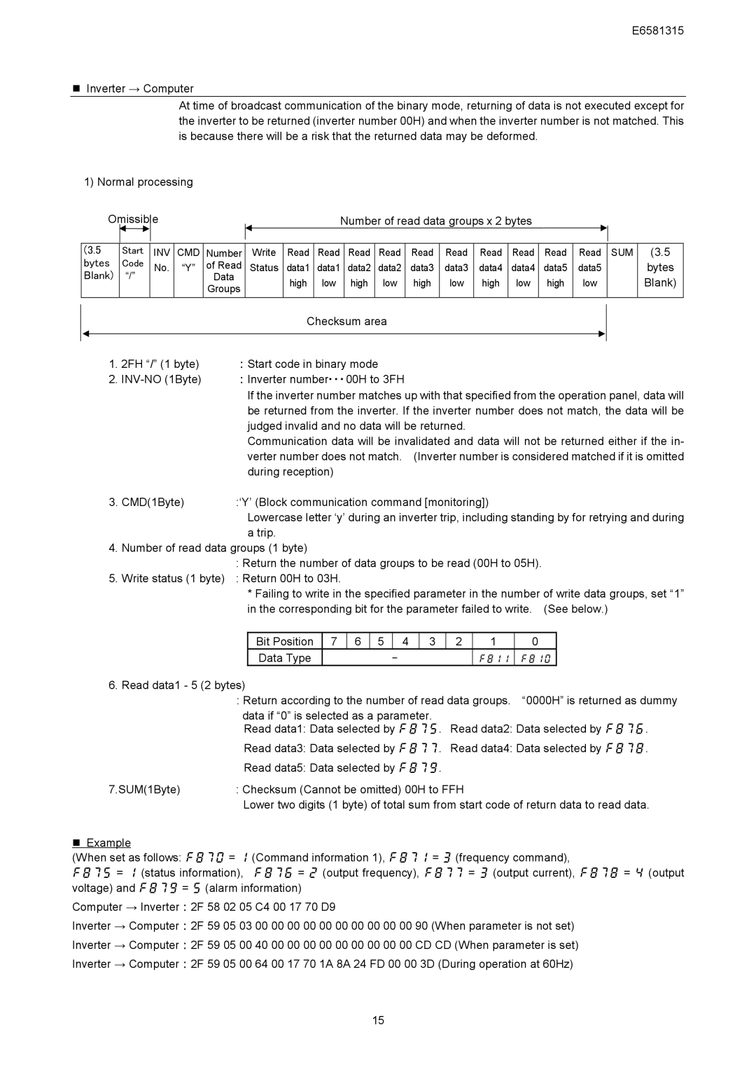
1) Normal processing

Omissible


Number of read data groups x 2 bytes


(3.5 bytes Blank)

Start Code

“/”

INV CMD No. “Y”

Number

Write

Read

Read

Read

Read

Read

Read

Read

Read

Read

Read

SUM

of Read

Status

data1

data1

data2

data2

data3

data3

data4

data4

data5

data5


Data


high

low

high

low

high

low

high

low

high

low


Groups


(3.5

bytes

Blank)

Checksum area

1.2FH “/” (1 byte) Start code in binary mode

2.INV-NO (1Byte) Inverter number・・・00H to 3FH

If the inverter number matches up with that specified from the operation panel, data will be returned from the inverter. If the inverter number does not match, the data will be judged invalid and no data will be returned.

Communication data will be invalidated and data will not be returned either if the in- verter number does not match. (Inverter number is considered matched if it is omitted during reception)

3. CMD(1Byte)

:‘Y’ (Block communication command [monitoring])


Lowercase letter ‘y’ during an inverter trip, including standing by for retrying and during

atrip.

4.Number of read data groups (1 byte)

:Return the number of data groups to be read (00H to 05H).

5. Write status (1 byte) : Return 00H to 03H.

*Failing to write in the specified parameter in the number of write data groups, set “1” in the corresponding bit for the parameter failed to write. (See below.)

Bit Position

7

6

5


4

3

2

1

0

Data Type






6.Read data1 - 5 (2 bytes)

:Return according to the number of read data groups. “0000H” is returned as dummy

data if “0” is selected as a parameter.

Read data1: Data selected by . Read data2: Data selected by .

Read data3: Data selected by . Read data4: Data selected by .

Read data5: Data selected by .

7.SUM(1Byte) : Checksum (Cannot be omitted) 00H to FFH

Lower two digits (1 byte) of total sum from start code of return data to read data.

„Example

(When set as follows:  =  (Command information 1),  =  (frequency command),

 =  (status information), =  (output frequency),  =  (output current),  =  (output voltage) and  =  (alarm information)

Computer → Inverter2F 58 02 05 C4 00 17 70 D9

Inverter → Computer2F 59 05 03 00 00 00 00 00 00 00 00 00 00 90 (When parameter is not set)

Inverter → Computer2F 59 05 00 40 00 00 00 00 00 00 00 00 00 CD CD (When parameter is set)

Inverter → Computer2F 59 05 00 64 00 17 70 1A 8A 24 FD 00 00 3D (During operation at 60Hz)

15

Page 16
Image 16
Toshiba RS485, VF-AS1 Series instruction manual Bytes Blank Start Code

RS485, VF-AS1 Series specifications

The Toshiba VF-AS1 Series represents a significant advancement in the realm of variable frequency drives (VFDs), designed for various industrial applications that demand precision, efficiency, and reliability. With support for RS485 communication, the VF-AS1 Series fosters seamless integration into complex automation systems, making it the perfect choice for modern manufacturing environments.

One of the standout features of the Toshiba VF-AS1 Series is its versatile communication capabilities. The built-in RS485 port allows for easy connectivity with a range of devices, including PLCs (Programmable Logic Controllers) and HMIs (Human-Machine Interfaces). This ensures real-time monitoring and control of motor functions, enhancing operational efficiency and data analysis.

The VF-AS1 Series is engineered with advanced control technologies that provide exceptional motor performance. It incorporates vector control algorithms that optimize torque and speed regulation for both standard and permanent magnet motors. This results in precise motor control across a wide range of speeds and load conditions, ensuring optimum performance and energy savings.

Another noteworthy characteristic is its user-friendly interface. The VF-AS1 features a clear LCD display that allows for easy navigation and configuration. This intuitive design minimizes the learning curve for operators and technicians, facilitating quick setup and adjustments. Additionally, the series supports various programming options, catering to both novice users and experienced professionals.

Energy efficiency is a key priority in the design of the VF-AS1 Series. The drives are equipped with energy-saving features that help reduce overall power consumption and operational costs. With built-in sleep modes and dynamic energy feedback, these drives optimize energy usage based on demand, making them suitable for both constant and variable load applications.

In terms of safety and protection, the VF-AS1 Series incorporates various built-in safeguards, including overvoltage, undervoltage, and overcurrent protection. This comprehensive approach to safety not only protects the drive itself but also ensures the longevity of connected equipment.

Overall, the Toshiba VF-AS1 Series, with its robust feature set, advanced technologies, and focus on energy efficiency, proves to be a reliable choice for a wide range of industrial applications. Its integration of RS485 communication allows for enhanced connectivity and control, making it an excellent solution for modern automation needs.