RS485, VF-AS1 Series specifications
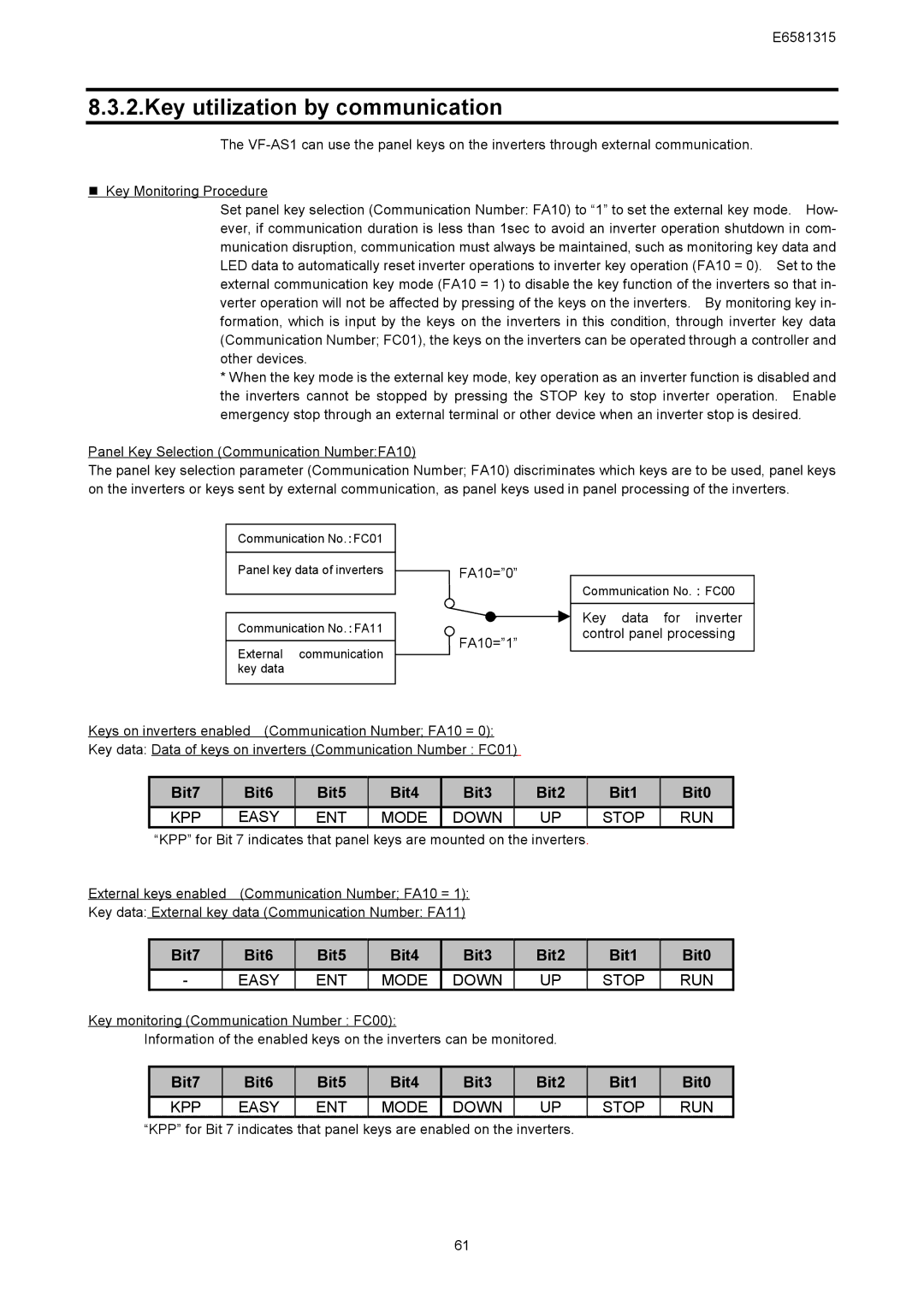
The Toshiba VF-AS1 Series represents a significant advancement in the realm of variable frequency drives (VFDs), designed for various industrial applications that demand precision, efficiency, and reliability. With support for RS485 communication, the VF-AS1 Series fosters seamless integration into complex automation systems, making it the perfect choice for modern manufacturing environments.One of the standout features of the Toshiba VF-AS1 Series is its versatile communication capabilities. The built-in RS485 port allows for easy connectivity with a range of devices, including PLCs (Programmable Logic Controllers) and HMIs (Human-Machine Interfaces). This ensures real-time monitoring and control of motor functions, enhancing operational efficiency and data analysis.
The VF-AS1 Series is engineered with advanced control technologies that provide exceptional motor performance. It incorporates vector control algorithms that optimize torque and speed regulation for both standard and permanent magnet motors. This results in precise motor control across a wide range of speeds and load conditions, ensuring optimum performance and energy savings.
Another noteworthy characteristic is its user-friendly interface. The VF-AS1 features a clear LCD display that allows for easy navigation and configuration. This intuitive design minimizes the learning curve for operators and technicians, facilitating quick setup and adjustments. Additionally, the series supports various programming options, catering to both novice users and experienced professionals.
Energy efficiency is a key priority in the design of the VF-AS1 Series. The drives are equipped with energy-saving features that help reduce overall power consumption and operational costs. With built-in sleep modes and dynamic energy feedback, these drives optimize energy usage based on demand, making them suitable for both constant and variable load applications.
In terms of safety and protection, the VF-AS1 Series incorporates various built-in safeguards, including overvoltage, undervoltage, and overcurrent protection. This comprehensive approach to safety not only protects the drive itself but also ensures the longevity of connected equipment.
Overall, the Toshiba VF-AS1 Series, with its robust feature set, advanced technologies, and focus on energy efficiency, proves to be a reliable choice for a wide range of industrial applications. Its integration of RS485 communication allows for enhanced connectivity and control, making it an excellent solution for modern automation needs.

