3.3. Installation Conditions
15°
15°
15 °
15°
15°
15°
15°
15 °
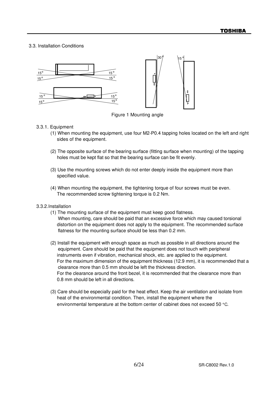
30 ° | 15 ° |
|
|
|
|
|
|
|
|
|
| ||
|
|
|
|
|
|
|
|
|
|
|
|
|
|
|
|
|
|
|
|
|
|
|
|
|
|
|
|
|
|
|
|
|
|
|
|
|
|
|
|
|
|
|
|
|
|
|
|
|
Figure 1 Mounting angle
3.3.1.Equipment
(1)When mounting the equipment, use four M2-P0.4 tapping holes located on the left and right sides of the equipment.
(2)The opposite surface of the bearing surface (fitting surface when mounting) of the tapping holes must be kept flat so that the bearing surface can be fit evenly.
(3)Use the mounting screws which do not enter deeply inside the equipment more than specified value.
(4)When mounting the equipment, the tightening torque of four screws must be even.
The recommended screw tightening torque is 0.2 Nm.
3.3.2.Installation
(1)The mounting surface of the equipment must keep good flatness.
When mounting, care should be paid that an excessive force which may caused torsional distortion on the equipment does not apply to the equipment. The recommended surface flatness for the mounting surface should be less than 0.2 mm.
(2)Install the equipment with enough space as much as possible in all directions around the equipment. Care should be paid that the equipment does not touch with peripheral instruments even if vibration, mechanical shock, etc. are applied to the equipment.
For the maximum dimension of the equipment thickness (12.9 mm), it is recommended that a clearance more than 0.5 mm should be left the thickness direction.
For the clearance around the front bezel, it is recommended that the clearance more than 0.8 mm should be left in all directions.
(3)Care should be especially paid for the heat effect. Keep the air ventilation and isolate from heat of the environmental condition. Then, install the equipment where the environmental temperature at the bottom center of cabinet does not exceed 50 °C.
6/24 |
|