Adjusting the picture automatically

CONTENTS

34

Remote control


ON /


STANDBY


INPUT


KEYSTONE

AUTO SET

2


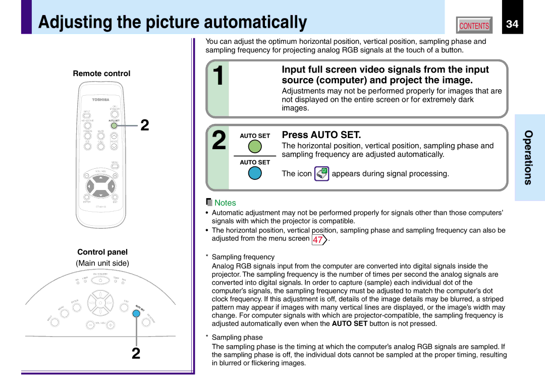
You can adjust the optimum horizontal position, vertical position, sampling phase and sampling frequency for projecting analog RGB signals at the touch of a button.

1

Input full screen video signals from the input

source (computer) and project the image.

Adjustments may not be performed properly for images that are not displayed on the entire screen or for extremely dark images.

FREEZE

MUTE


PIP

CALL

RESIZE

MENU

VOL / ADJ

2 AUTO SET

AUTO SET

Press AUTO SET.

The horizontal position, vertical position, sampling phase and sampling frequency are adjusted automatically.

The icon appears during signal processing.

Operations

ENTEREXIT

CT-90113

Control panel (Main unit side)


ON / STANDBY


P


T

EMP


ON

LAM


F


AN


TE


EXI


EN

R


T


U


A


UT


N


O

S


E


M


ET


K


T


E


S


U


Y


N

P


T

I


O


N


VOL / ADJ


E


2

Notes

Automatic adjustment may not be performed properly for signals other than those computers’ signals with which the projector is compatible.

The horizontal position, vertical position, sampling phase and sampling frequency can also be adjusted from the menu screen 47.

*Sampling frequency

Analog RGB signals input from the computer are converted into digital signals inside the projector. The sampling frequency is the number of times per second the analog signals are converted into digital signals. In order to capture (sample) each individual dot of the computer’s signals, the sampling frequency must be adjusted to match the computer’s dot clock frequency. If this adjustment is off, details of the image details may be blurred, a striped pattern may appear if images with many vertical lines are displayed, or the image’s width may change. For computer signals with which are projector-compatible, the sampling frequency is adjusted automatically even when the AUTO SET button is not pressed.

*Sampling phase

The sampling phase is the timing at which the computer’s analog RGB signals are sampled. If the sampling phase is off, the individual dots cannot be sampled at the proper timing, resulting in blurred or flickering images.

Page 34
Image 34
Toshiba TLP380, TLP381 Adjusting the picture automatically, Input full screen video signals from the input, Press Auto SET

TLP381, TLP380 specifications

The Toshiba TLP380 and TLP381 are advanced optoisolators designed for various applications requiring reliable isolation and switching control. These devices are particularly valuable in communication, industrial, and consumer electronics, where signal integrity and noise immunity are crucial.

The TLP380 is a phototransistor optoisolator, featuring a gallium arsenide infrared LED and a phototransistor. With a minimum isolation voltage of 5,000 VRMS, it provides high voltage isolation between input and output, making it an excellent choice for protecting sensitive components from high voltages and surges. The TLP380 offers a high-speed switching capability, with a rise time of around 4 μs, enabling it to transmit signals efficiently in digital circuits.

On the other hand, the TLP381 is also a phototransistor optoisolator but specifically optimized for lower input current, making it more power-efficient. It offers similar isolation voltage ratings and switching characteristics to the TLP380, but with a lower input current threshold, which can be particularly advantageous in battery-powered applications. The lower current requirement helps extend battery life and minimizes power consumption in portable devices.

Both TLP380 and TLP381 devices feature a wide temperature range, making them suitable for various environmental conditions. Their operating temperature ranges from -40°C to +100°C, ensuring reliable performance under extreme conditions. Additionally, with their compact DIP packages, they are easy to integrate into crowded PCB layouts, making them a preferred choice for designers targeting space-constrained applications.

In terms of characteristics, both models provide low output voltage saturation and high-speed operation, which are critical in achieving fast response times in control circuits. The combination of robust isolation, efficient power consumption, and temperature stability makes the TLP380 and TLP381 versatile solutions for isolating signals in a myriad of electronic systems.

In summary, the Toshiba TLP380 and TLP381 optoisolators are engineered for high-performance signal isolation, offering superior technologies and characteristics that cater to a range of applications. Their reliability, efficiency, and compact design make them a compelling choice for engineers and designers looking to enhance their electronic systems.