Installer’s Guide
3.Attach center hose of manifold gauges to vacuum pump.
4.Evacuate until the micron gauge reads no higher than 350 microns.
5.Close off valve to vacuum pump and observe the micron gauge. If gauge pressure rises above 500 microns in one
(1)minute, then evacuation is incomplete or system has a leak.
6.If vacuum gauge does not rise above 500 microns in one
(1)minute, the evacuation should be complete.
7.With vacuum pump and micron gauge blanked off, open valve on
NOTE:
DO NOT VENT REFRIGERANT INTO THE ATMOSPHERE.
8.Close valve on
NOTE:
A 3/16" Allen wrench is required to open liquid line service valve. A 1/4" Open End or Adjustable wrench is required to open gas line valve. A 3/4" Open End wrench is required to take off the valve stem cap.
9.The liquid line
10.Replace liquid service pressure tap port cap and valve stem cap. These caps MUST BE REPLACED to prevent leaks. Replace valve stem and pressure tap cap finger tight, then tighten an additional 1/6 turn.
11.The gas valve can now be opened. For a ball type gas valve, open the gas valve by removing the
12.The gas valve is now open for refrigerant flow. Replace valve stem cap to prevent leaks. Again, these caps MUST BE REPLACED to prevent leaks. Replace valve stem and pressure tap cap finger tight, then tighten an additional 1/6 turn. See Figure 4.
If refrigerant lines are longer than 15 feet and/or a different size than recommended, it will be necessary to adjust system refrigerant charge upon completion of installation. See unit Service Facts.
▲! WARNING
When installing or servicing this equipment, ALWAYS exercise basic safety precautions to avoid the possibility of electric shock.
1.Power wiring and grounding of equipment must comply with local codes.
2.Power supply must agree with equipment nameplate.
3.Install a separate disconnect switch at the outdoor unit.
4.Ground the outdoor unit per local code requirements.
5.Provide flexible electrical conduit whenever vibration transmission may create a noise problem within the structure.
6.The use of color coded low voltage wire is recommended to simplify connections between the outdoor unit, the thermostat and the indoor unit.
Table 1
| 24 VOLTS | |
|
|
|
WIRE SIZE |
| MAX. WIRE LENGTH |
|
|
|
18 AWG |
| 150 FT |
|
|
|
16 AWG |
| 225 FT. |
|
|
|
14 AWG |
| 300 FT. |
|
|
|
7.Table 1 defines maximum total length of low voltage wiring from outdoor unit, to indoor unit, and to thermostat.
8.Mount the indoor thermostat in accordance with instruc- tion included with the thermostat. Wire per appropriate
G.DEFROST CONTROL
The demand defrost control measures heat pump outdoor ambient temperature with a sensor located outside the outdoor coil. A second sensor located on the outdoor coil is used to measure the coil temperature. The difference be- tween the ambient and the colder coil temperature is the difference or
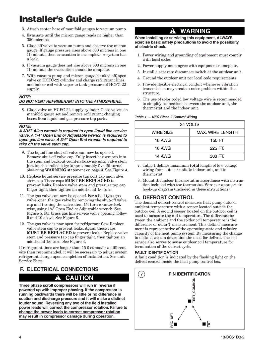
FAULT IDENTIFICATION
A fault condition is indicated by the flashing light on the defrost control inside the heat pump control box.
F. ELECTRICAL CONNECTIONS
▲! CAUTION
Three phase scroll compressors will run in reverse if powered up with improper phasing. If the compressor is running backwards there will be little or no difference in suction and discharge pressure and it will make a distinct louder sound. Reversing any two of the field installed power leads will correct the compressor rotation. Failure to change the power leads to correct compressor rotation may result in compressor damage during operation.
7
PIN IDENTIFICATION
| TEST COMMON |
FRC DFT | TST |
4 |