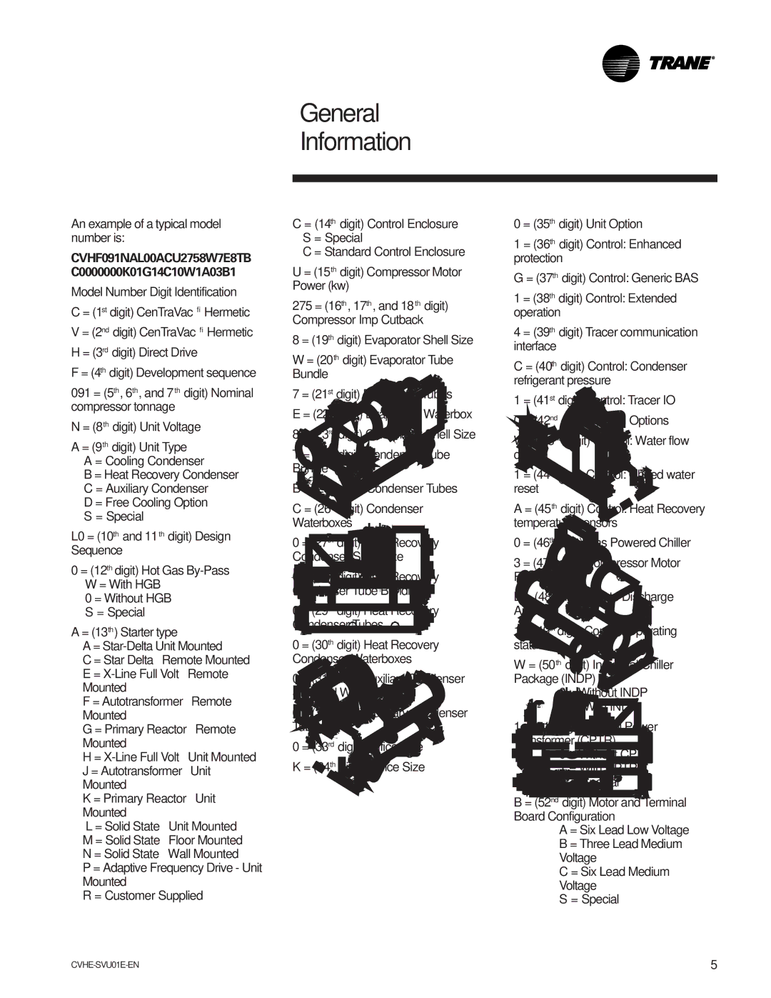
CVHE-SVU01E-ENX39640712050 specifications
The Trane CVHE-SVU01E-ENX39640712050 is a high-efficiency centrifugal chiller designed for commercial and industrial applications. This state-of-the-art unit is engineered to provide reliable cooling performance, energy efficiency, and optimized operational flexibility. It is particularly suitable for large-scale facilities that require significant cooling capacity and robust performance under varying load conditions.One of the most notable features of the CVHE-SVU01E series is its advanced variable speed drive technology. This technology enables the chiller to adjust its speed according to the cooling demands of the facility, resulting in substantial energy savings. By operating at optimal speeds, this unit reduces power consumption and enhances overall efficiency. This is noteworthy in the context of rising energy costs and increasing sustainability demands across various industries.
Moreover, the CVHE-SVU01E is equipped with Trane’s proprietary Compliant Scroll compressor technology. This innovative compressor design minimizes mechanical losses and increases the efficiency of the chiller system. Additionally, the compressor is specifically designed to handle varying refrigerant flow rates, allowing the chiller to maintain performance even when faced with fluctuating conditions.
Another significant characteristic of this chiller model is its use of environmentally friendly refrigerants, aligning with global regulations aimed at reducing greenhouse gas emissions. This commitment to sustainability ensures that the CVHE-SVU01E not only provides excellent cooling performance but also adheres to contemporary environmental standards.
The unit utilizes an advanced control system that simplifies operation and enhances troubleshooting capabilities. The intuitive interface allows facility managers to monitor performance metrics, optimize operation schedules, and conduct remote diagnostics, significantly reducing costly downtime and maintenance efforts.
Furthermore, the compact and modular design of the CVHE-SVU01E makes it easy to install in various settings. Its durability is ensured through the use of high-quality materials and components, designed to withstand the rigors of demanding environments. With reduced maintenance requirements, facility operators can focus on core business functions without frequent interruptions.
In summary, the Trane CVHE-SVU01E-ENX39640712050 combines cutting-edge technologies and features to deliver exceptional performance, efficiency, and reliability in commercial cooling applications. Its advanced design contributes to reduced energy costs, minimal environmental impact, and greater operational flexibility, making it an excellent choice for organizations seeking sustainable and efficient cooling solutions.

