Controls

Control wiring

The control circuit is 24 V AC. Unit includes a 400/24 V transformer.

WARNING! The unit disconnect switch must be opened and locked open. Risk of injury and electrocution.

CAUTION! The unit 24 V transformer must not be used to power accessories mounted on site, other than those proposed by Trane.

Unit controlled by thermostat

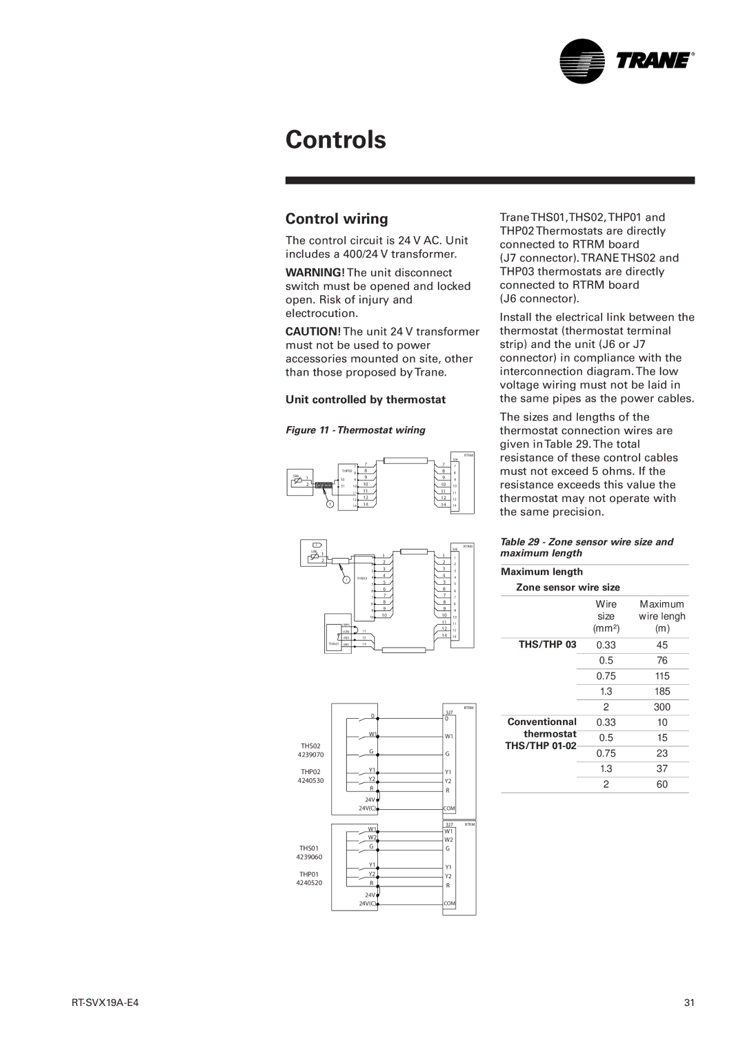
Figure 11 - Thermostat wiring


RTRM


3J6


7

7


7

7


SR6


THP03 8

8


8

8


1

S2

9

9


9

9


2

S1

10

10


10

10


11

11


11

11


12

12


12

12


14

14


14

14


1


RTRM


SR6 1


3J6


1

1

1

1


2


2

2

2

2


3

3

3

3


1


THS03 4

4

4

4


5

5


5

5


6

6

6

6


7

7


7

7


8

8

8

8


9

9

9

9


10

10

10

10


(WH)


11

11


12


(GN)


11


12


14


(RD)


12


14


THA01

(BK)


14


3J7

RTRM


0


0


W1


W1


THS02


G


4239070


G


THP02


Y1


Y1


4240530


Y2


Y2


R


R


24V


24V(C)


COM


W1


3J7

RTRM


W1


W2


W2


G


THS01


G


4239060


Y1


Y1


THP01


Y2


Y2


4240520


R


R


24V


24V(C)


COM


Trane THS01,THS02, THP01 and THP02 Thermostats are directly connected to RTRM board

(J7 connector). TRANE THS02 and THP03 thermostats are directly connected to RTRM board

(J6 connector).

Install the electrical link between the thermostat (thermostat terminal strip) and the unit (J6 or J7 connector) in compliance with the interconnection diagram. The low voltage wiring must not be laid in the same pipes as the power cables.

The sizes and lengths of the thermostat connection wires are given in Table 29. The total resistance of these control cables must not exceed 5 ohms. If the resistance exceeds this value the thermostat may not operate with the same precision.

Table 29 - Zone sensor wire size and maximum length

Maximum length

Zone sensor wire size


Wire

Maximum


size

wire lengh


(mm²)

(m)


THS/THP 03

0.33

45


0.5

76


0.75

115


1.3

185


2

300


Conventionnal

0.33

10

thermostat


0.5

15

THS/THP 01-02


0.75

23


1.3

37


2

60


RT-SVX19A-E4

31

Page 31
Image 31
Trane RT-SVX19A-E4 manual Control wiring, Unit controlled by thermostat, Zone sensor wire size and maximum length

RT-SVX19A-E4 specifications

The Trane RT-SVX19A-E4 is a groundbreaking rooftop unit designed for versatile commercial heating and cooling applications. This model stands out for its innovative technology and robust features, making it a preferred choice for many businesses seeking efficient climate control solutions.

One of the primary characteristics of the RT-SVX19A-E4 is its exceptional energy efficiency. It utilizes advanced variable-speed technology, allowing it to adjust the compressor's output based on real-time demand. This not only reduces energy consumption significantly but also provides more accurate temperature control, enhancing overall comfort within the space. The unit is designed with high-efficiency fan motors and optimized heat exchangers, which contribute to its impressive Seasonal Energy Efficiency Ratio (SEER) and Energy Efficiency Ratio (EER) ratings.

The Trane RT-SVX19A-E4 also features a robust and durable design, built to withstand a variety of weather conditions. Its all-weather cabinet protects the internal components from environmental stresses, ensuring longevity and reliable performance. The unit is equipped with corrosion-resistant materials that enhance its durability, making it suitable for both coastal and urban environments.

Another notable feature is its advanced control system. The RT-SVX19A-E4 comes with Trane's IntelliPak controls, which provide users with precise monitoring and management capabilities. This smart control system enables remote access via internet connectivity, allowing facility managers to monitor performance, adjust settings, and diagnose issues in real-time, improving operational efficiency and reducing maintenance costs.

Additionally, the RT-SVX19A-E4 offers a range of customization options. It can be tailored to meet specific operational needs, with various configurations available for air flow, heating, and cooling needs. This flexibility ensures organizations can find a solution that best fits their requirements, whether it be for an office building, retail space, or industrial facility.

In conclusion, the Trane RT-SVX19A-E4 represents a significant advancement in rooftop HVAC technology, combining energy efficiency, durability, and intelligent controls. Its ability to adapt to varying demands, coupled with customizable options, makes it an excellent investment for businesses looking to enhance their indoor climate while minimizing energy expenses.