
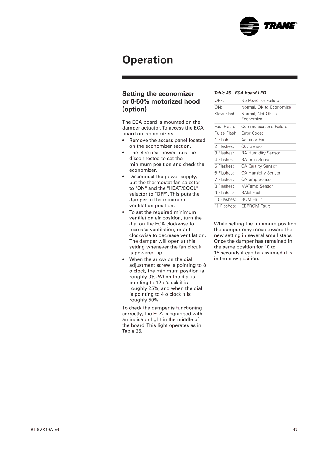
RT-SVX19A-E4 specifications
The Trane RT-SVX19A-E4 is a groundbreaking rooftop unit designed for versatile commercial heating and cooling applications. This model stands out for its innovative technology and robust features, making it a preferred choice for many businesses seeking efficient climate control solutions.One of the primary characteristics of the RT-SVX19A-E4 is its exceptional energy efficiency. It utilizes advanced variable-speed technology, allowing it to adjust the compressor's output based on real-time demand. This not only reduces energy consumption significantly but also provides more accurate temperature control, enhancing overall comfort within the space. The unit is designed with high-efficiency fan motors and optimized heat exchangers, which contribute to its impressive Seasonal Energy Efficiency Ratio (SEER) and Energy Efficiency Ratio (EER) ratings.
The Trane RT-SVX19A-E4 also features a robust and durable design, built to withstand a variety of weather conditions. Its all-weather cabinet protects the internal components from environmental stresses, ensuring longevity and reliable performance. The unit is equipped with corrosion-resistant materials that enhance its durability, making it suitable for both coastal and urban environments.
Another notable feature is its advanced control system. The RT-SVX19A-E4 comes with Trane's IntelliPak controls, which provide users with precise monitoring and management capabilities. This smart control system enables remote access via internet connectivity, allowing facility managers to monitor performance, adjust settings, and diagnose issues in real-time, improving operational efficiency and reducing maintenance costs.
Additionally, the RT-SVX19A-E4 offers a range of customization options. It can be tailored to meet specific operational needs, with various configurations available for air flow, heating, and cooling needs. This flexibility ensures organizations can find a solution that best fits their requirements, whether it be for an office building, retail space, or industrial facility.
In conclusion, the Trane RT-SVX19A-E4 represents a significant advancement in rooftop HVAC technology, combining energy efficiency, durability, and intelligent controls. Its ability to adapt to varying demands, coupled with customizable options, makes it an excellent investment for businesses looking to enhance their indoor climate while minimizing energy expenses.