Field
Wiring
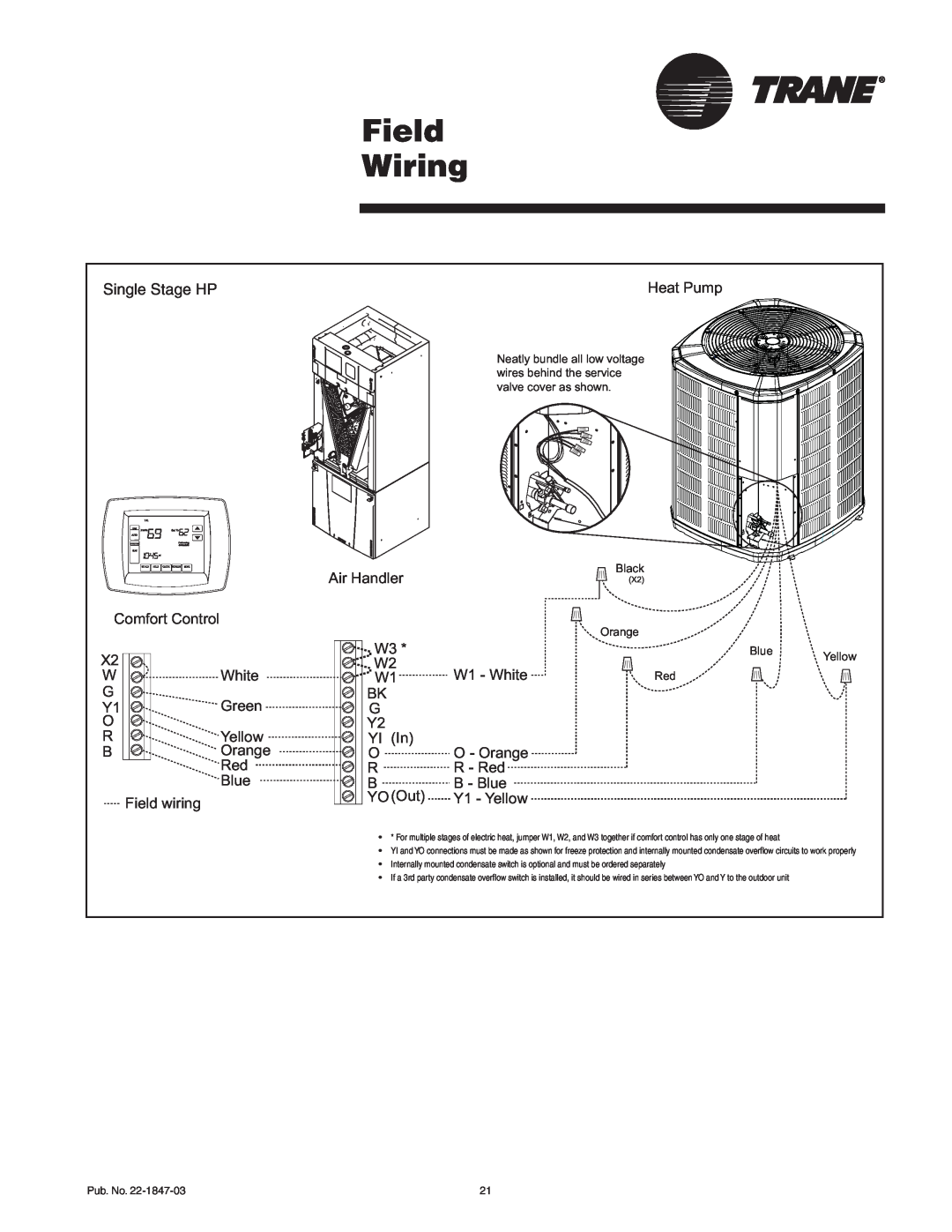
Single Stage HP | Heat Pump |
Comfort Control |
|
X2 | White |
W | |
G | Green |
Y1 | |
O | Yellow |
R | |
B | Orange |
| Red |
| Blue |
Field wiring |
|
Air Handler
W3 *
W2
W1
BK
G
Y2
YI (In)
O
R
B
YO (Out)
Neatly bundle all low voltage wires behind the service valve cover as shown.
Black
(X2)
Orange
Blue Yellow
W1 - WhiteRed
O - Orange
R - Red
B - Blue
Y1 - Yellow
•• * For multiple stages of electric heat, jumper W1, W2, and W3 together if comfort control has only one stage of heat
•• YI and YO connections must be made as shown for freeze protection and internally mounted condensate overflow circuits to work properly
•• Internally mounted condensate switch is optional and must be ordered separately
•• If a 3rd party condensate overflow switch is installed, it should be wired in series between YO and Y to the outdoor unit
Pub. No. | 21 |