BAS-SVP10A-EN, Trane Communicating Thermostats (BACnet) specifications
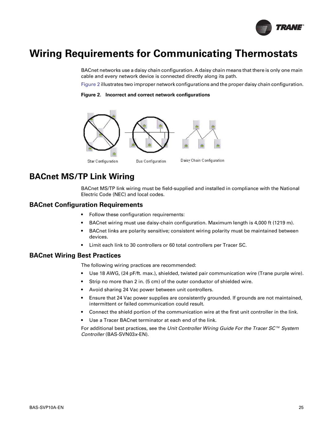
The Trane BAS-SVP10A-EN is a part of the Trane Communicating Thermostats series designed to facilitate efficient and effective building temperature control in HVAC systems. These thermostats work with BACnet (Building Automation and Control Network), a widely adopted communication protocol in building automation for networked control of HVAC systems, lighting, access control, and fire systems.One of the standout features of the Trane BAS-SVP10A-EN is its compatibility with various Trane equipment and other BACnet-compliant devices. This versatility allows for seamless integration into existing building systems, enhancing operational efficiency. The thermostat is designed to support zoning applications, offering precise temperature control to individual areas or rooms, thus significantly improving occupant comfort while also minimizing energy consumption.
The Trane communicating thermostat is built with advanced technologies that ensure optimal performance. It utilizes digital communication, enabling real-time data exchange between the thermostat and the HVAC system. This capability enhances the responsiveness of the HVAC system, allowing it to adjust more accurately to changing environmental conditions. The thermostat features an intuitive interface with a clear display, making it user-friendly for building occupants and facility managers alike.
Another important characteristic is its advanced scheduling capabilities. Users can program customized heating and cooling schedules, promoting energy savings while maintaining comfort levels. Additionally, its remote access feature allows for monitoring and control from smartphones, tablets, or computers, making it convenient for users to manage their HVAC systems from virtually anywhere.
The Trane BAS-SVP10A-EN also boasts robust diagnostic and reporting functions. It can provide feedback on system performance, enabling proactive maintenance and troubleshooting, which increases the reliability of HVAC operations. Overall, the Trane Communicating Thermostat represents a sophisticated solution for modern building management, focusing on comfort, energy efficiency, and ease of integration into existing systems. With its commitment to leveraging cutting-edge technology, Trane continues to lead in providing innovative solutions for heating, ventilation, and air conditioning needs in diverse building environments.

