INSTALLATION (continued)
Install Slide-In-Module in PointSystem™ Chassis
CAUTION: Any
NOTE: Install Media Converter
1. | Carefully slide Media Converter |
| aligning Media Converter |
| NOTE: Ensure that |
2. | Secure |
Power the
NOTE: The
Center™.
OPERATION
After installation, the media converter should function without operator intervention.
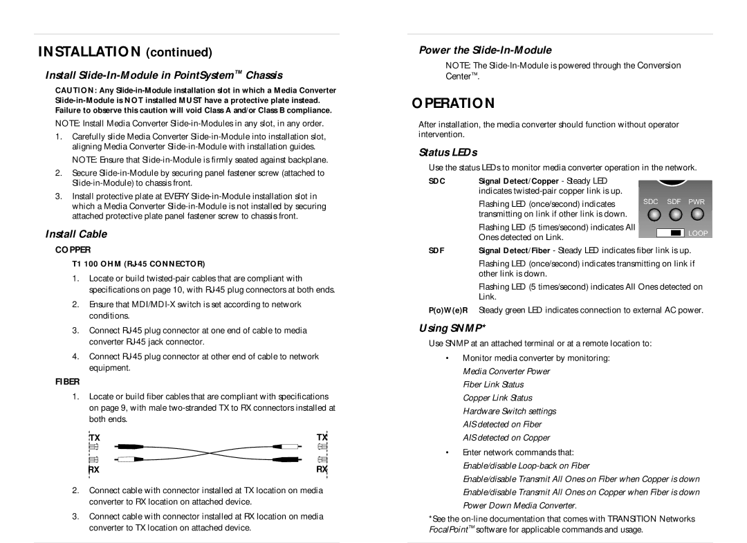
Status LEDs
Use the status LEDs to monitor media converter operation in the network.
3. Install protective plate at EVERY |
which a Media Converter |
attached protective plate panel fastener screw to chassis front. |
Install Cable
SDC | Signal Detect/Copper - Steady LED |
| indicates |
| Flashing LED (once/second) indicates |
| transmitting on link if other link is down. |
| Flashing LED (5 times/second) indicates All |
| Ones detected on Link. |
SDC SDF PWR
![]()
![]()
![]()
![]() LOOP
LOOP
COPPER
T1 100 OHM (RJ-45 CONNECTOR)
1.Locate or build
2.Ensure that
3.Connect
4.Connect
FIBER
1.Locate or build fiber cables that are compliant with specifications on page 9, with male
TX | TX |
RX | RX |
2.Connect cable with connector installed at TX location on media converter to RX location on attached device.
3.Connect cable with connector installed at RX location on media converter to TX location on attached device.
SDF | Signal Detect/Fiber - Steady LED indicates fiber link is up. |
| Flashing LED (once/second) indicates transmitting on link if |
| other link is down. |
| Flashing LED (5 times/second) indicates All Ones detected on |
| Link. |
P(o)W(e)R | Steady green LED indicates connection to external AC power. |
Using SNMP*
Use SNMP at an attached terminal or at a remote location to:
•Monitor media converter by monitoring: Media Converter Power
Fiber Link Status Copper Link Status Hardware Switch settings AIS detected on Fiber AIS detected on Copper
•Enter network commands that: Enable/disable
Enable/disable Transmit All Ones on Fiber when Copper is down Enable/disable Transmit All Ones on Copper when Fiber is down Power Down Media Converter.
*See the