E-TBT-MC04 specifications
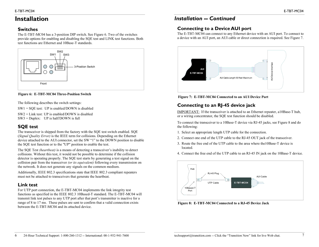
Transition Networks E-TBT-MC04 is a highly specialized network device designed to facilitate the seamless integration of Ethernet networks into existing infrastructures. This media converter, part of Transition Networks’ broad portfolio of networking solutions, stands out for its reliability and adaptability, making it an excellent choice for organizations looking to upgrade their connectivity options without entirely overhauling their systems.One of the primary features of the E-TBT-MC04 is its capability to convert twisted pair signals (10/100/1000BASE-T) to fiber optic signals (100BASE-FX). This functionality allows businesses to extend their network ranges significantly, overcoming the limitations posed by traditional copper cabling. With a maximum transmission distance of up to 2 kilometers via multimode fiber, the E-TBT-MC04 ensures that data can be reliably transmitted over longer distances without the susceptibility to signal interference that commonly affects copper connections.
Equipped with a variety of technologies, the E-TBT-MC04 supports both full-duplex and half-duplex communication modes, enabling it to accommodate a wide range of applications. Additionally, the device features automatic negotiation capabilities, allowing it to detect the speed of connected devices and adapt accordingly. This feature ensures that users benefit from optimal performance, regardless of the specific infrastructure already in place.
The E-TBT-MC04 also includes advanced features such as link fault pass-through (LFP), which aids in maintaining network integrity by detecting failures and providing alerts. This proactive monitoring is crucial for businesses that require high uptime and reliability from their network components. Furthermore, the media converter operates as a stand-alone device, making it easy to install and manage without the need for complex configurations or additional software.
In terms of physical characteristics, the E-TBT-MC04 is designed with ruggedness in mind, making it suitable for both indoor and outdoor deployments. Its compact design allows for easy placement in various environments, while the durable construction ensures longevity even in challenging conditions.
Overall, the Transition Networks E-TBT-MC04 is a versatile and efficient solution that meets the growing demand for high-speed, reliable network connectivity. Its combination of advanced technologies, extensive compatibility, and robust design makes it an ideal choice for organizations that are looking to modernize their networking capabilities while maintaining a focus on performance and reliability.

