4 Making Network Connections
2.If the device is a PC card and the switch is in the wiring closet, attach the other end of the cable segment to a modular wall outlet that is connected to the wiring closet. (See “Network Wiring Connections” on page
Make sure each twisted pair cable does not exceed 100 meters (328 ft) in length.
3.As each connection is made, the Link LED (on the switch) corresponding to each port will light to indicate that the connection is valid.
Note: Avoid using flow control on a port connected to a hub unless it is actually required to solve a problem. Otherwise back pressure jamming signals may degrade overall performance for the segment attached to the hub.
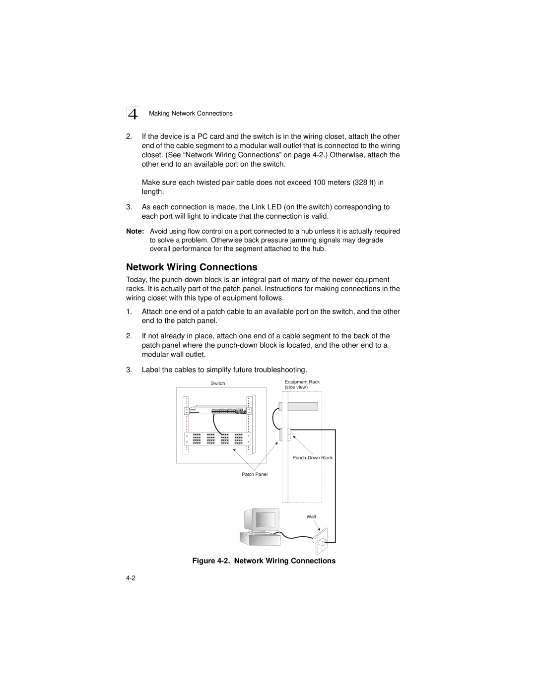
Network Wiring Connections
Today, the
1.Attach one end of a patch cable to an available port on the switch, and the other end to the patch panel.
2.If not already in place, attach one end of a cable segment to the back of the patch panel where the
3.Label the cables to simplify future troubleshooting.
Switch |
Patch Panel
Equipment Rack (side view)
Wall |