SSDTF10xx-10x
|
|
|
|
|
|
|
|
|
|
|
|
Part Number |
|
|
| Port | One - Copper |
| Port Two - Single Fiber Optic | ||||
|
|
|
|
|
|
|
|
|
|
|
|
|
|
|
| SC, 1310 mn (TX)/1550 nm (RX) | |||||||
|
|
|
|
| 1.5 km (5,000 feet)* |
| single mode, 20 km (12.4 miles)* | ||||
|
|
|
|
|
|
|
|
|
| ||
|
|
|
|
|
|
|
|
|
| ||
** |
|
|
|
| SC, 1550 mn (TX)/1310 nm (RX) | ||||||
|
| ||||||||||
|
|
|
|
| 1.5 km (5,000 feet)* |
| single mode, 20 km (12.4 miles)* | ||||
|
|
|
|
|
|
|
| ||||
*** |
|
|
|
|
| SC, 1310 mn (TX)/1550 nm (RX) | |||||
|
|
|
|
| 1.5 km (5,000 feet)* |
| single mode, 40 km (24.8 miles)* | ||||
*** |
| SC, 1550 mn (TX)/1310 nm (RX) | |||||||||
1.5 km (5,000 feet)* | single mode, 40 km (24.8 miles)* |
| (TX) = transmit (RX) = receive |
Installation
CAUTION: Wear a grounding device and observe electrostatic discharge precautions when setting the jumper and switches. Failure to observe this caution could result in damage to, and subsequent failure of, the device.
Set the hardware/software jumper
The hardware/software jumper is located on the circuit board inside the device housing.
* | Typical maximum cable distance. Actual distance is dependent upon the physical |
| characteristics of the network. |
** | |
| one is the local device and the other is the remote device. |
*** | |
| one is the local device and the other is the remote device. |
Hardware: | The device mode is determined by the |
| switch settings. |
Software: | The device mode is determined by the |
| |
| microprocessor settings. |
To set the
H ![]()
![]()
![]()
![]()
![]()
![]()
![]()
![]()
![]() S
S
Hardware Mode
H ![]()
![]()
![]()
![]()
![]()
![]()
![]()
![]()
![]() S
S
Software Mode
Note: The chassis version of the device is
Optional Accessories (sold separately)
Part Number | Description |
|
Optional External Power Supply; |
| |
| Output: 12.6VDC, 1.0 A |
|
|
|
|
Optional External Power Supply; |
| |
| Output: 12.6VDC, 1.0 A |
|
|
|
|
| ||
| 15 x 5 in. (432 x 381 x 127 mm) |
|
|
|
|
WMBL | Optional Wall Mount Brackets |
|
1.Using a small screwdriver, remove the four (4) screws that secure the cover and carefully remove the cover from the device.
2.The jumper is located on the circuit board and is labeled “H” and “S”.
3.Using small
4.Carefully replace the cover on the device and replace the four (4) screws that secure the cover to the device.
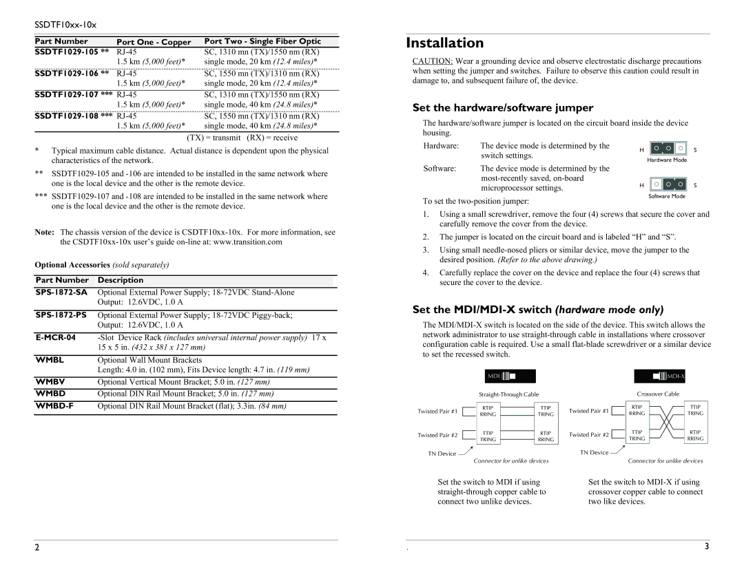
Set the MDI/MDI-X switch (hardware mode only)
The
| Length: 4.0 in. (102 mm), Fits Device length: 4.7 in. (119 mm) |
WMBV | Optional Vertical Mount Bracket; 5.0 in. (127 mm) |
WMBD | Optional DIN Rail Mount Bracket; 5.0 in. (127 mm) |
| Optional DIN Rail Mount Bracket (flat); 3.3in. (84 mm) |
|
|
MDI 


Twisted Pair #1 |
|
| RTIP |
| TTIP |
|
| ||||
|
| RRING |
| TRING | |
Twisted Pair #2 |
|
| TTIP |
| RTIP |
|
| ||||
|
|
| TRING |
| RRING |
|
|
|
TN Device ![]()
Connector for unlike devices
Twisted Pair #1
Twisted Pair #2
TN Device ![]()
|
|
|
| |
|
|
|
| |
|
|
|
|
|
| Crossover Cable |
| ||
|
|
| ||
RTIP |
|
| TTIP | |
RRING |
| TRING | ||
TTIP |
| RTIP | ||
TRING |
| RRING | ||
|
|
|
|
|
Connector for unlike devices
Set the switch to MDI if using |
| Set the switch to |
| crossover copper cable to connect | |
connect two unlike devices. |
| two like devices. |
|
|
|
|
|
|
2 | . | 3 |