SSDTF10xx-10x
Installation -- Continued
Install the copper cable
1.Locate or build
2.Ensure that the
3.Connect the
4.Connect the
|
|
|
|
|
|
|
|
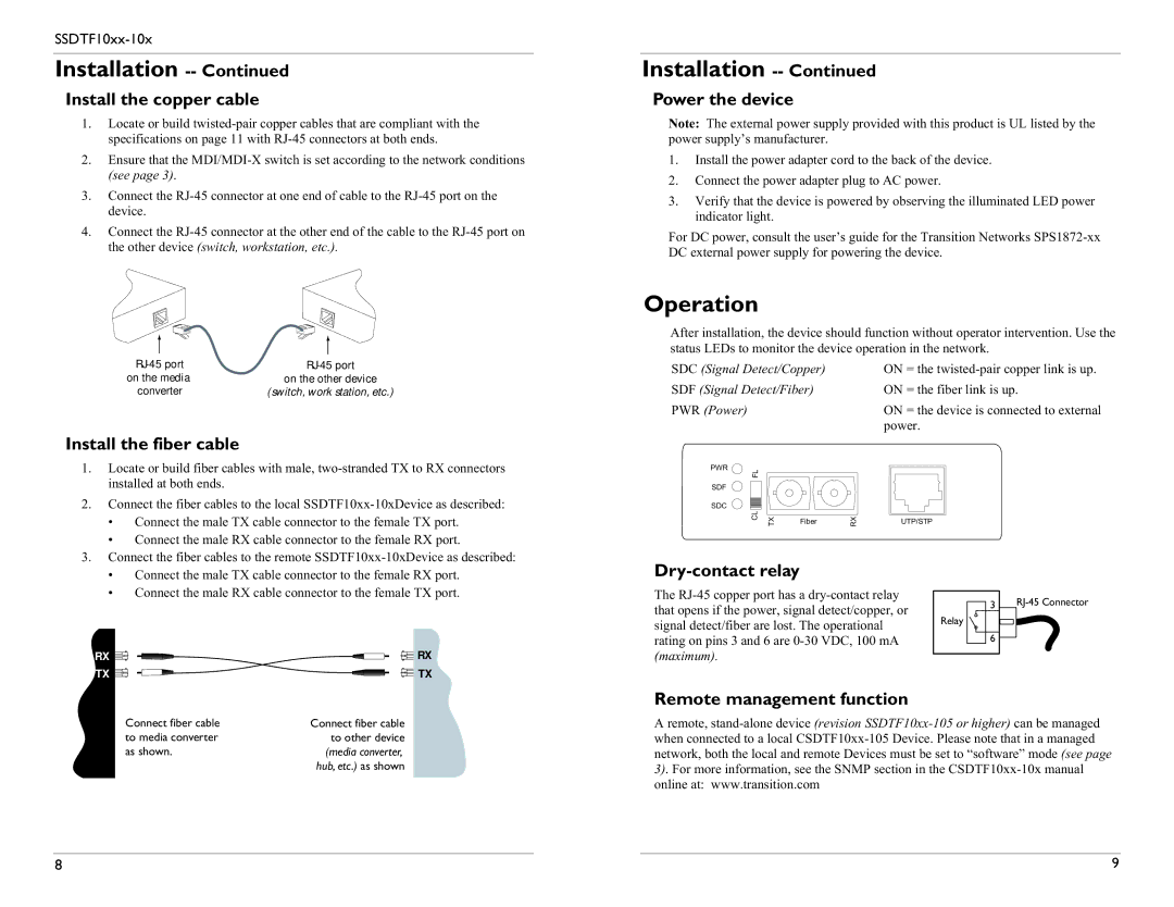
on the media | on the other device | ||
converter | (switch, work station, etc.) | ||
|
|
|
|
Install the fiber cable
1. | Locate or build fiber cables with male, | |
| installed at both ends. | |
2. | Connect the fiber cables to the local | |
| • | Connect the male TX cable connector to the female TX port. |
| • | Connect the male RX cable connector to the female RX port. |
3. | Connect the fiber cables to the remote | |
Installation -- Continued
Power the device
Note: The external power supply provided with this product is UL listed by the power supply’s manufacturer.
1.Install the power adapter cord to the back of the device.
2.Connect the power adapter plug to AC power.
3.Verify that the device is powered by observing the illuminated LED power indicator light.
For DC power, consult the user’s guide for the Transition Networks
Operation
After installation, the device should function without operator intervention. Use the status LEDs to monitor the device operation in the network.
SDC (Signal Detect/Copper) |
| ON = the | |||
SDF (Signal Detect/Fiber) |
| ON = the fiber link is up. | |||
PWR (Power) |
|
|
|
| ON = the device is connected to external |
|
|
|
|
| power. |
PWR | FL |
|
|
|
|
|
|
|
|
| |
SDF |
|
|
|
|
|
SDC | CL |
|
|
|
|
| TX | Fiber | RX | UTP/STP | |
• | Connect the male TX cable connector to the female RX port. |
• | Connect the male RX cable connector to the female TX port. |
RX | RX |
TX | TX |
Dry-contact relay
The
Relay
3
6
Connect fiber cable | Connect fiber cable |
to media converter | to other device |
as shown. | (media converter, |
| hub, etc.) as shown |
Remote management function
A remote,
8 | 9 |