Electrical connections
Before connecting the appliance, check that the vol- tage quoted on the rating plate - that is, the nominal vol- tage of the appliance - corresponds to the available mains voltage. The rating plate can be found on the lower housing of the ceramic glass hob.
The mains connection must be carried out by an expert electrician. The
Prior to connection it should be checked whether the voltage stated on the type plate
The heating element voltage amounts to 230 V ~. The appliance will also perfectly perform with the former mains voltage of 220 V ~.
The mains connection must be carried out in a way that an
A wire of type
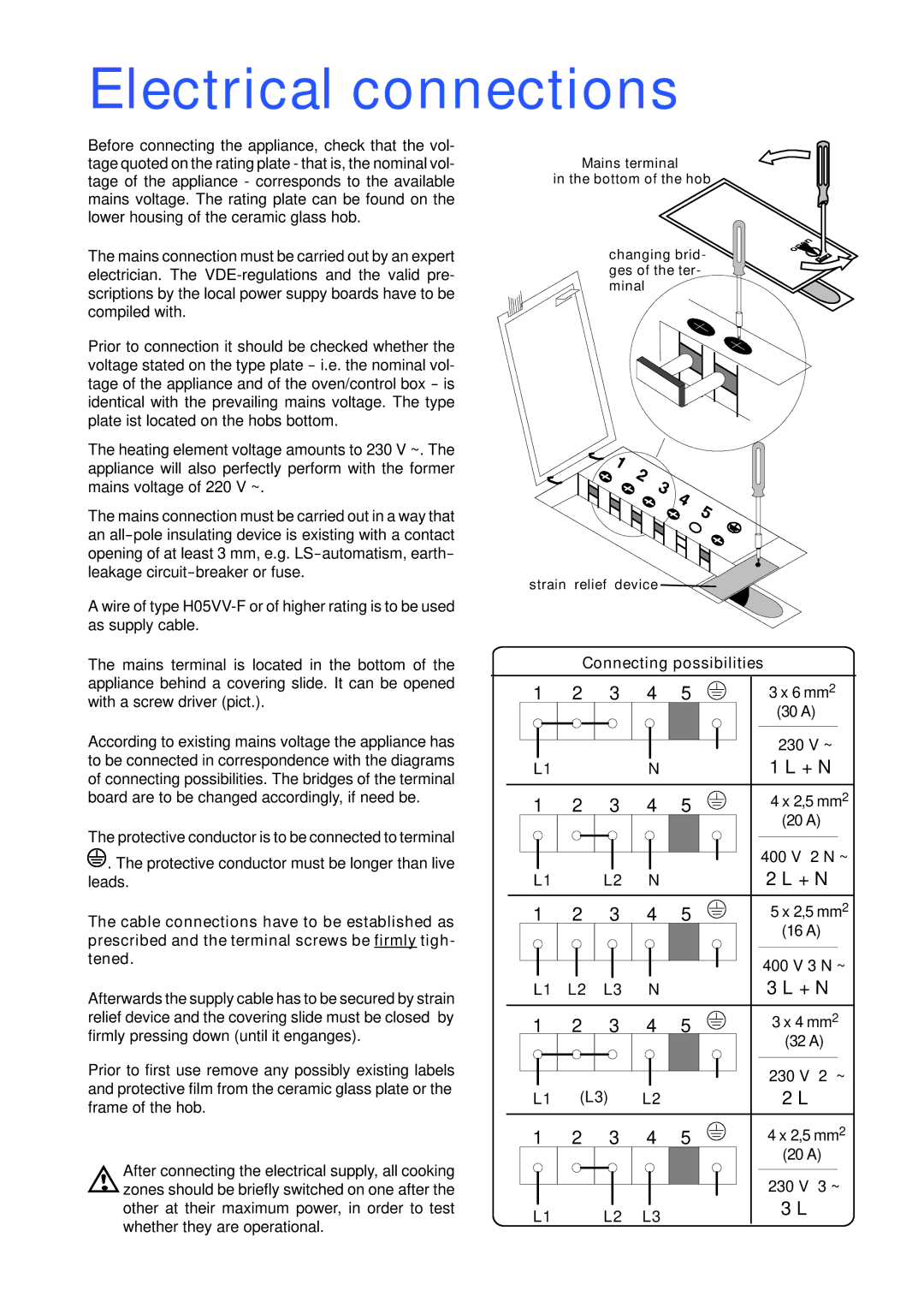
The mains terminal is located in the bottom of the appliance behind a covering slide. It can be opened with a screw driver (pict.).
According to existing mains voltage the appliance has to be connected in correspondence with the diagrams of connecting possibilities. The bridges of the terminal board are to be changed accordingly, if need be.
The protective conductor is to be connected to terminal
![]() . The protective conductor must be longer than live leads.
. The protective conductor must be longer than live leads.
The cable connections have to be established as prescribed and the terminal screws be firmly tigh- tened.
Afterwards the supply cable has to be secured by strain relief device and the covering slide must be closed by firmly pressing down (until it enganges).
Prior to first use remove any possibly existing labels and protective film from the ceramic glass plate or the frame of the hob.
After connecting the electrical supply, all cooking zones should be briefly switched on one after the other at their maximum power, in order to test whether they are operational.
Mains terminal
in the bottom of the hob
changing brid- ges of the ter- minal
strain relief device ![]()
![]()
Connecting possibilities
1 | 2 | 3 | 4 | 5 | 3 x 6 mm2 |
|
|
|
|
| (30 A) |
|
|
|
|
| 230 V ~ |
L1 |
|
| N |
| 1 L + N |
1 | 2 | 3 | 4 | 5 | 4 x 2,5 mm2 |
|
|
|
|
| (20 A) |
|
|
|
|
| 400 V 2 N ~ |
L1 |
| L2 | N |
| 2 L + N |
1 | 2 | 3 | 4 | 5 | 5 x 2,5 mm2 |
|
|
|
|
| (16 A) |
|
|
|
|
| 400 V 3 N ~ |
L1 | L2 | L3 | N |
| 3 L + N |
1 | 2 | 3 | 4 | 5 | 3 x 4 mm2 |
|
|
|
|
| (32 A) |
|
|
|
|
| 230 V 2 ~ |
L1 | (L3) | L2 |
| 2 L | |
1 | 2 | 3 | 4 | 5 | 4 x 2,5 mm2 |
|
|
|
|
| (20 A) |
|
|
|
|
| 230 V 3 ~ |
L1 |
| L2 | L3 |
| 3 L |
|
|
| |||