Quick Installation
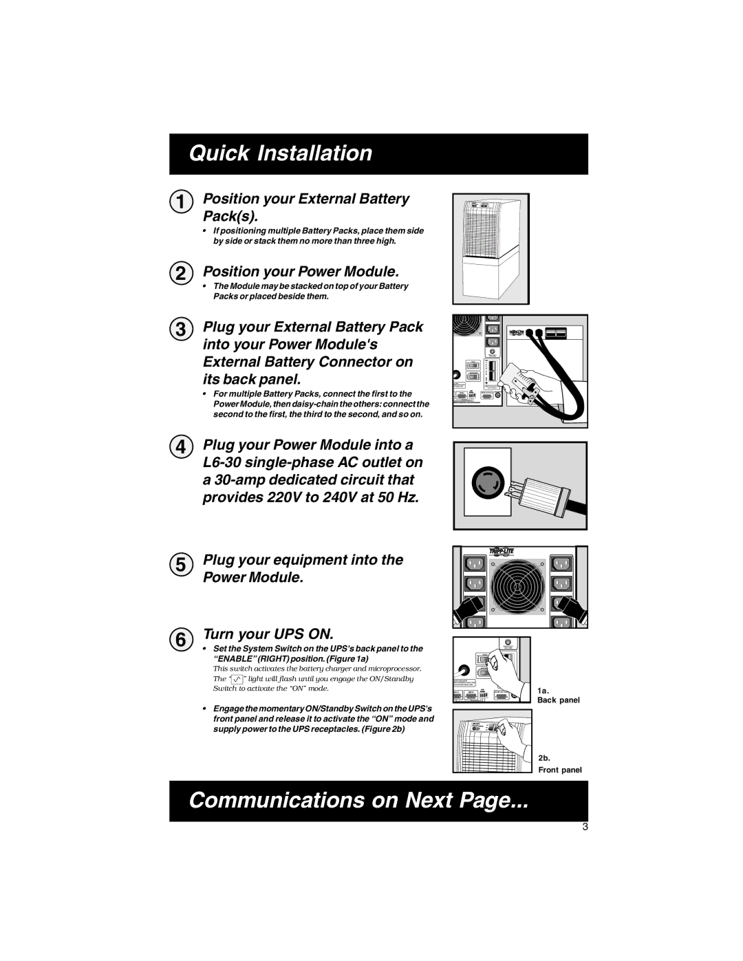
1 Position your External Battery Pack(s).
•If positioning multiple Battery Packs, place them side by side or stack them no more than three high.
2 Position your Power Module.
•The Module may be stacked on top of your Battery Packs or placed beside them.
3 Plug your External Battery Pack into your Power Module's External Battery Connector on its back panel.
•For multiple Battery Packs, connect the first to the Power Module, then
| BRANCH CIRCUIT #1 |
| 230VAC 10AMPS |
00VA 4500W |
|
M 50/60HZ 5000VA 3700W | CAUTION: DO NOT UNPLUG WHILE |
50HZ 5000VA 3700W | OPERATING OR ARCING WILL OCCUR |
| 36VDC 175 AMPS MAX |
4 Plug your Power Module into a
5 | Plug your equipment into the |
|
| Power Module. |
|
6 | Turn your UPS ON. |
|
• Set the System Switch on the UPS's back panel to the | 230VAC 10AMPS | |
|
| BRANCH CIRCUIT #1 |
| “ENABLE” (RIGHT) position. (Figure 1a) |
|
| This switch activates the battery charger and microprocessor. |
|
| The “ ” light will flash until you engage the ON/Standby | 30VAC NOM 50/60HZ 5000VA 3700W |
|
| 50/60HZ 5000VA 4500W |
| Switch to activate the “ON” mode. | 0VAC NOM 50HZ 5000VA 3700W |
| 1a. | |
| • Engage the momentary ON/Standby Switch on the UPS's | Back panel |
|
| |
| front panel and release it to activate the “ON” mode and |
|
| supply power to the UPS receptacles. (Figure 2b) |
|
|
| 2b. |
|
| Front panel |
Communications on Next Page...
3